65
ADJUSTMENT
ENGLISH
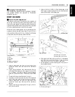
12. If at full speed the machine pulls one direction or the
other, it is an indication that one wheel is turning faster
than the other.
To adjust the condition, proceed as follows:
(1) Park the machine on a firm and level surface.
(2) Stop the engine.
(3) Loosen the front bolt of faster side.
(4) Move the speed adjust plate to backward.
(5) Tighten the front bolt securely.
B
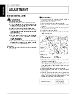
MOTION CONTROL LEVER FORCE
The force required to move the motion control levers can
be adjusted to one of 3 levels depending on operator
preference.
A
Adjust the dampers after adjusting HST neutral.
A
Adjusting the motion control lever force will affect the
maneuverability.
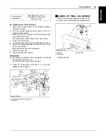
1. Change the upper side of the damper to the desired
hole location.
Tighten the upper side damper nut.
2. Loosen the nut on the bottom side of damper.
3. Move the motion control lever to the rearmost position
and release the motion control lever.
4. After the motion control lever and damper have
stopped moving, place motion control lever in
"NEUTRAL LOCK" position.
(1) Speed adjust plate
(2) Bolt
(A) Motion control lever
Tightening torque
23.6 to 27.4 N-m
(2.4 to 2.8 kgf-m,
17.4 to 20.2 lbf-ft)
(1) Damper
(2) Nut
(A) "LIGHTER"
(B) "HEAVIER"
(H1) Hole for lighter setting
(H2) Hole for heavier setting
(1) Motion control lever
(2) Damper
(3) Nut
(A) "IT STOPS MOVING"
(B) "NEUTRAL LOCK" position
(C) "TIGHTEN"
Summary of Contents for Z723
Page 7: ......
Page 13: ...SAFE OPERATION 6 ENGLISH 5 DANGER WARNING AND CAUTION LABELS ...
Page 14: ... 7 SAFE OPERATION ENGLISH ...
Page 15: ...SAFE OPERATION 8 ENGLISH ...
Page 16: ... 9 SAFE OPERATION ENGLISH ...
Page 19: ...SERVICING OF MACHINE 2 ENGLISH 1 ROPS serial No ...


