ASSEMBLY
OM 0427SBC-A
18
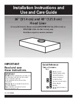
Figure 16
Figure 17
Figure 18
Connecting the Driveline to the Snowblower
(Figures 16 to 18)
1. Figure 16:
Install the 1/4” x 1/4" x 1 1/2"
key (item 1) on the reduction box shaft
(item 2) then connect the driveline male
half (item 3) to the reduction box shaft
(item 2) and secure in place with a 1/4"NC
x 2 1/2" hex bolt and 1/4" nylon insert lock
nut (items 4-5). Using thread locker, install
the 3/8" x 3/8" allen setscrew (item 6) on
the driveline.
2. Figure 17:
Place one nylon flat washer
(item 2) between the driveline guard (item 3)
and the grease panel (item 1) and secure
with a 5/16" x 3/4" hex bolt and a 5/16"
stover lock nut (items 4-5). The grease
panel (item 1) should move freely, but be
tight enough to keep it in place.
3. Figure 17:
Install the driveline guard
(item 3) on the reduction box with two
7/16"NC x 3/4" hex bolts and 7/16"
lockwashers (items 7-8). Use the top hole
on the left side of the guard.
4. Figure 18:
Install a 5/32" x 1" cotter pin
(item 1) on the driveline support rod (item 2)
and
into the guard bushing (item 3). Install
the compression spring, 5/16” flat washer
and plastic knob (items 4-5- 6).
WARNING:
This shaft turns at very
high RPM. If the collar is not locked to the
shaft at tractor end, or if the yoke at the
blower end is not secured properly, the
driveline can fly loose with great force
capable of causing serious injury or death.
CAUTION:
In order to ensure that the
driveline or other parts are not damaged,
DO NOT WORK with the driveline placed on
its support (see figure 20a).
Summary of Contents for L4474
Page 33: ...ELECTRICAL DIAGRAM OM 0427SBC A 31 ELECTRICAL DIAGRAM ...
Page 36: ...PARTS OM 0427SBC A 34 SNOWBLOWER FIG 000200_RAD1511015 ...
Page 38: ...PARTS OM 0427SBC A 36 SNOWBLOWER CONT D FIG 000300_RAD1511016 ...
Page 42: ...PARTS OM 0427SBC A 40 HYDRAULIC SYSTEM FIG 000600_RAD1511018 ...
Page 52: ...Printed in Canada ...