background image

17

CHECKS BEFORE START

B

When the Check-up is Completed

When the check-up is completed, perform the following
procedure to make the Periodic Check disappear from the
screen.
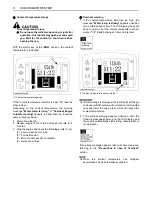
1. The message below appears onscreen to prompt the

completion of the check-up.

2. To take a look at the check points, press the

information switch. The check points appear
onscreen.

3. When the check-up has been completed, press the

switch 5. If not, press the switch 1 to go back to the
previous screen.

B

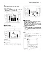
Horn Switch

B

Light Switch

When the starter switch is in position "RUN", the working
light(s) and CAB light(s) will be switched on by pressing
the switch.

C

Night operation

To avoid personal injury: 

A

When the working light and CAB light alone do
not provide sufficient visibility, prepare
additional stationary artificial lighting and
observe safety rules for night work.

B

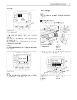
AUX Port Flow Rate Limit Switch

It is possible to freely readjust the actuator's maximum
flow rate in the AUX operating mode.
(See 

"AUX PORT OPERATION"

 section for detail.)

(1) Switch 4
(2) Switch 1
(3) Switch 5

(1) Horn switch

(1) Light switch

(1) AUX port flow rate limit switch

Summary of Contents for KX080-4

Page 1: ...123 Taman Perindustrian Axis Seksyen 25 40400 Shah Alam Selan or Darul Ehsan Malaysia Telephone 60 3 736 1388 Philippines KUBOTA PHILIPPINES INC 232 Quirino Hi hway Baesa Quezon City 1106 Philippines...

Page 2: ...d dozer ABBREVIATION LIST California Proposition 65 WARNING Engine exhaust some of its constituents certain vehicle components and fluids contain or emit chemicals known to the State of California to...

Page 3: ...o Idle AI Lamp Indicator lamp Glow Working light switch Horn Wiper Washer switch Diesel Hydraulic fluid Gear oil Grease Fast Slow Excavator Overhead movement toward the front Excavator Overhead moveme...

Page 4: ...tes a potentially hazardous situation which if not avoided could result in minor or moderate injury Indicates that equipment or property damage could result if instructions are not followed This symbo...

Page 5: ...splayed at a Glance on a Single Screen 15 When the Check up is Completed 17 Horn Switch 17 Light Switch 17 AUX Port Flow Rate Limit Switch 17 Auto Idle Switch 18 Throttle Potentiometer 18 Travel Speed...

Page 6: ...n Turn 34 UP AND DOWNHILL DRIVING 35 PARKING ON A SLOPE 35 OPERATION OF THE DOZER 35 TWO PATTERN SELECTION SYSTEM TPSS 36 Pattern Change 36 OPERATION OF THE BOOM 37 OPERATION OF THE ARM 37 OPERATION O...

Page 7: ...er 70 REGULAR CHECKS AND MAINTENANCE WORK 71 EVERY 50 SERVICE HOURS 71 Draining the Water from the Fuel Tank 71 Draining Water Separator 71 Battery 72 Battery Charging 73 Greasing Swing Bearing Teeth...

Page 8: ...ses 86 Checking Boost Sensor and AFS Air Flow Sensor 86 Checking Condition of Diesel Particulate Filter DPF Muffler 86 Checking Diesel Particulate Filter DPF Differential Pressure Sensor and Piping fo...

Page 9: ...S 96 PREPARATION FOR OPERATION IN COLD WEATHER 96 PROCEDURE AFTER DONE WORK 96 LONG STORAGE 97 RECOMMENDED OILS 99 APPENDICES 101 MAIN DIMENSIONS 101 LIFTING CAPACITY 102 LIST OF SCREENS 104 LIST OF N...

Page 10: ......

Page 11: ...combination will reduce the risk of serious injury or death should the excavator be upset or falling objects occur Do not modify any structural members of the ROPS OPG Top Guard Level I by welding dr...

Page 12: ...by law or statutes 12 Do not allow passengers to ride on any part of the excavator at anytime The operator must remain in the excavator seat during operation 13 Check levers pedals and all mechanical...

Page 13: ...e dozer blade is in front of you If the levers are activated with the dozer blade at the rear the tracks will move in the opposite direction of the drive levers 5 Do not operate or idle engine in a no...

Page 14: ...en to play on the machine or on the attachments 7 Use extra caution when backing up Look behind and down to make sure the area clear before moving 8 When parking your machine if at all possible park o...

Page 15: ...remove the key When dismantling hydraulic parts make sure that the hydraulic oil has cooled down sufficiently to avoid burns Start maintenance work carefully e g loosen plug slowly so that oil will no...

Page 16: ...opriately 12 Observe all laws and regulations concerning the disposal of used oil coolants solvents hydraulic fluids battery acids and batteries 13 To avoid fire do not heat the hydraulic components t...

Page 17: ...due to heat from the regeneration If such occurs activate the inhibit switch 26 Fire prevention Excavator and some attachments have components that are at high temperatures under normal operating con...

Page 18: ...SAFE OPERATION 8...

Page 19: ...9 SAFE OPERATION...

Page 20: ...SAFE OPERATION 10...

Page 21: ...11 SAFE OPERATION...

Page 22: ...SAFE OPERATION 12...

Page 23: ...13 SAFE OPERATION...

Page 24: ...nger warning and caution labels with new labels from your KUBOTA dealer 4 If a component with danger warning and caution label s affixed is replaced with new part make sure new label s is are attached...

Page 25: ...The Product s described in this Operator s Manual are designed and manufactured only for the country in which they are initially wholesaled by Kubota or one of its affiliated companies Neither Kubota...

Page 26: ...e Type Water cooled 4 cycle diesel engine with 4 cylinder Model name KUBOTA V3307 CR TE4 Total displacement cc cu in 3331 203 3 Engine power SAE gross kW Hp 49 7 66 6 SAE net kW Hp 46 5 62 3 Rated spe...

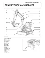
Page 27: ...CONTENTS 1 Arm 2 Bucket cylinder 3 Bucket link 2 and 3 4 Bucket link 1 5 Bucket 6 Boom cylinder 7 Dozer cylinder 8 Dozer blade 9 Arm cylinder 10 Boom 11 Working light 12 Cabin 13 Operator s seat 14 Sw...

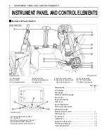
Page 28: ...DPF inhibit switch 11 Beacon light switch Ref page Starter switch 6 LCDdisplay 7 Fuel gauge Water temperature gauge Hour meter Engine tachometer Glow lamp User setting switch AUX port enable switch In...

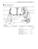
Page 29: ...ever left 3 Boom swing pedal 4 Drive lever right 5 Attachment control lever right 6 Dozer control lever 7 Drive pedal left 8 Drive pedal right Ref page Drive lever left 33 Attachment control lever lef...

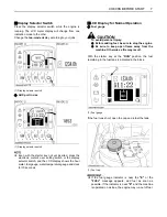
Page 30: ...ROPS OPG Top Guard Level I for damage and if damage is found contact your KUBOTA dealer for repair CHECKING THE DEVICES BStarter Switch A STOP The key can be inserted at the STOP position A RUN Turn t...

Page 31: ...clock for 10 seconds BLCD Display for Normal Operation C Fuel gauge To avoid personal injury A Before adding fuel be sure to stop the engine A Be sure to keep open flame away from the machine Otherwi...

Page 32: ...ion 3 Mud or dust deposits on radiator 4 Hydraulic oil leak C Overheat warning 1 If the coolant temperature becomes too high the message Water temp is Rising appears onscreen for a certain period of t...

Page 33: ...warning lamp is used to indicate broken wire short circuit fuel shortage and other problems The warning lamp starts flashing in red if any problem occurs If the system senses a in warning signal the w...

Page 34: ...RUN position without starting the engine and the charging lamp stays off the charging system has failed If such occurs immediately contact your local dealer for repair C Engine oil pressure low warni...

Page 35: ...ation switch and a detail such as shown below appears A Press the information switch again and the display goes back to the previous screen A If you have any question consult your KUBOTA Dealer BSetti...

Page 36: ...onth day hour and minute will be selected in this order 4 Save the new setting with the switch Switch 5 Press this switch 5 again to set the clock Status after setting the clock A Be careful not to ac...

Page 37: ...ered 2 Using the switch 4 move the cursor to Side B Select the AM PM system or the 24 hour system 3 Press the switch 5 and the new settings will be made If the switch 1 is pressed the previous setting...

Page 38: ...he following message appears on the LCD display 10 hours before a periodic check Press the switch 4 to see the check results Do the following servicing listed below A When the servicing has been compl...

Page 39: ...RE START BIf All the Check Points are not Displayed at a Glance on a Single Screen 1 Press the switch 4 2 Each time the switch 2 or 3 is pressed the check points scrolled up or down 1 Switch 4 2 Switc...

Page 40: ...J 4 change every 500 hrs 2 Hydraulic oil every 1000 hrs 3 Air filter element Outer element replace every 1000 hrs Inner element every 1000 hrs 4 Fuel filter every 500 hrs 5 Engine oil filter every 500...

Page 41: ...he previous screen BHorn Switch BLight Switch When the starter switch is in position RUN the working light s and CAB light s will be switched on by pressing the switch C Night operation To avoid perso...

Page 42: ...e travel speed switch The buzzer beeps twice and the travel speed changes from low to high The symbol lights up 2 Press the travel speed switch again and the buzzer beeps once and the travel speed cha...

Page 43: ...chine in this condition BInhibit Diesel Particulate Filter DPF Regeneration Switch Inhibit Diesel Particulate Filter DPF regeneration switch hereinafter called inhibit switch disables the Auto DPF reg...

Page 44: ...tion A further push on the switch will activate the washer system Even when the wiper switch is in the OFF position the washer switch functions if it is pressed A Do not activate the washer switch if...

Page 45: ...n A During summer turn the heater valve clockwise to close the valve BOpening Closing of CAB Door 1 Unlock the CAB door and pull the knob Open the CAB door fully until fixed into place 2 To close the...

Page 46: ...elf to let the windshield slide inward 3 Pull the windshield all the way to the lock at the back of CAB 4 To close the window take the reverse steps 3 2 and 1 BOpening Closing of Side CAB Window 1 Pul...

Page 47: ...t allow water to enter the fresh air port while washing the excavator BAir Control Vent C Front air outlet The front air outlets can be independently adjusted as required To defrost the windshield rot...

Page 48: ...rature control dial to the COOL or an intermediate position to achieve the desired temperature level A Be sure to close the door while the air conditioner is ON otherwise you may overload the compress...

Page 49: ...r more than 10 sec A If the engine does not start in 10 sec please wait 20 sec or more before attempting to restart STARTING THE ENGINE To avoid personal injury A The operator should not depend solely...

Page 50: ...attery is dead and must be connected to another battery with jumper cable be sure to use a 12V battery Never use a 24V batteries A If you keep the pilot control lock lever at UNLOCK and try to start t...

Page 51: ...flames away A Do not start the engine with an auxiliary battery if excavator battery is frozen A Do not connect the black jumper cable to the negative terminal of the excavator battery BObserve Follow...

Page 52: ...ne lubricant to warm up and penetrate every part of the engine 2 Once the engine has warmed up check A the warning lamp Engine oil pressure has gone out A the warning lamp Battery charge goes out when...

Page 53: ...rature gauge overheat condition take the following steps 1 Stop operating the machine Relieve the engine of any load 2 Do not shut off the engine suddenly Before shutting off the engine keep it idling...

Page 54: ...in so many fine metal particles are generated which can cause damage and shorten the life of many components Pay attention to the oil change intervals and complete them sooner than later See REGULAR...

Page 55: ...and body inside of the ROPS OPG Top Guard Level I protective A Do not touch the control levers and the pedals from outside the cab while the engine running BPilot Control Lock Lever To avoid personal...

Page 56: ...ont of the excavator A Use extra caution when traveling across a slope or working sideways on a slope A Recommended technique for working on a slope 1 Adjust the engine speed from idling to an interme...

Page 57: ...e excavator forwards and vice versa The front of the excavator is the side where the dozer is located the drive sprocket is in the rear of the excavator TURNS To avoid personal injury A Do not change...

Page 58: ...avator will turn in the direction of the arrow of the illustration below 2 Pull the left drive lever backward the excavator will turn in the direction of the arrow of the illustration below BSpin Turn...

Page 59: ...DOWNHILL TRAVELING PARKING ON A SLOPE To avoid personal injury or death A When the excavator is parked or left unattended on a slope be sure to put the bucket on the ground and place all control leve...

Page 60: ...e 1 Open the cover and position the pattern selector lever to the desired position 2 Close the cover 1 Pattern selector lever Two Pattern Selection System TPSS A Pattern A B Pattern B Lever Position P...

Page 61: ...e oil warms up To lower the boom push the attachment control lever forward A When lowering the boom make sure that it does not hit the dozer and that the bucket teeth do not touch the dozer OPERATION...

Page 62: ...e boom swing function is not used BUnit Swing Operation 1 Move the control lever to the left and the upper structure will turn to the left 2 Move the control lever to the right and the upper structure...

Page 63: ...can select one of them Up to five action modes can be preset Each time the AUX port enable switch switch 3 is pressed the action modes change over one after another And the icon and action mode number...

Page 64: ...play in AUX 1 and 2 modes BAUX Port Handling Procedure 1 Turn the starter key to the RUN position Let the engine warm up after start up for approx 10 minutes under no load conditions 2 Lower the pilot...

Page 65: ...and 2 modes If the machine is equipped with the AUX 1 port move the AUX port knob of the left attachment control lever to the right to send oil to the AUX port 3 Move the AUX port knob of the left at...

Page 66: ...he following message appears onscreen BSetting the Maximum Flow Volume The AUX port has been factory set to three action modes 1 2 and 3 The action modes 4 and 5 can also be preset C How to make the s...

Page 67: ...etting cursor arrow mark shifts position Move the cursor above the icon 5 Each time the switch 2 or 3 is pressed the icon changes Select your desired icons C Types of AUX icons 1 Icon 2 Mode No 3 Swit...

Page 68: ...action mode 1 Breaker icon for action mode 2 Disable icon for actions modes 3 4 and 5 Each time the AUX port enable switch switch 3 is pressed the display changes from action mode 1 action mode 2 to n...

Page 69: ...ual A Suppose that the same attachment is mounted on another machine Even if the same flow control setting is made the same speed cannot be achieved Make an optimum setting on each machine 8 Go back t...

Page 70: ...46 EXCAVATOR OPERATION...

Page 71: ...g the automatic regeneration A While a warning message like as Raise up engine speed is on the LCD display operator is requested to take directive procedure and take above procedure if operator requir...

Page 72: ...blade placed at an angle Stability of the machine is affected with blade at angle keep at neutral position Before starting the job position and keep the angle blade at the standard 0 marking Refer to...

Page 73: ...moving changing the equipment A Release pressure in the hydraulic system before removing changing the equipment See HOW TO RELEASE PRESSURE TRAPPED IN THE HYDRAULIC SYSTEM A Position the selection val...

Page 74: ...not activated the throttle potentiometer can be utilized to control engine speed in a similar way to a conventional throttle control lever A It is possible that the Auto Idle may not function until hy...

Page 75: ...monoxide Be careful not to make this setting in a room where the exhaust gases easily build up or in an ill ventilated place 1 Insert the red key into the key switch Do not turn the inserted key If th...

Page 76: ...y If the key is turned to the RUN position return it to the STOP position and return to the step 1 Then the message Pull out black key appears on the meter panel after a while With this message displa...

Page 77: ...rly A If an unregistered key is inserted and turned more than six times for one minute the alarm sounds for 30 seconds The alarm keeps sounding even if the key is drawn out D Insert and turn on the re...

Page 78: ...pulling in the bucket for driving or transportation avoid hitting the dozer A Avoid collisions When moving the excavator pay attention that the dozer does not collide with obstructions such as boulder...

Page 79: ...vehicle only with the arm completely pulled in A Do not jack up the machine using its boom to load or unload the excavator from the vehicle Doing this is dangerous Otherwise the CAB of the vehicle cou...

Page 80: ...the key 8 Raise the lock lever 9 Block the tracks with blocks and tie down the excavator B Towing the machine To avoid personal injury A When towing the excavator or pulling a load must be less than...

Page 81: ...in the middle of the hook 5 The load must be lifted vertically from the ground 6 Do not enter the working area under suspended loads and do not move the load over people The load must only be moved in...

Page 82: ...el wire 6X24 4 Lifting 1 Lift slowly and safely 2 Do not enter the excavator area when lifting 3 Lift the excavator horizontally Modify cable or strap connections according to needs Maximum strength f...

Page 83: ...tank drain every 50 hrs 71 11 Battery condition check every 50 hrs 72 12 Greasing swing bearing teeth every 50 hrs 73 13 V belt tension check Daily check 68 adjust every 200 hrs 74 14 Radiator hoses...

Page 84: ...50 hrs 71 11 Battery condition check every 50 hrs 72 12 Greasing swing bearing teeth every 50 hrs 73 13 V belt tension check Daily check 68 adjust every 200 hrs 74 14 Radiator hoses and clamps check...

Page 85: ...tial pressure sensor and piping for gas leak check every 1 year 86 4 34 DPF exhaust gas temperature sensor check every 1 year 86 4 35 EGR and piping for gas leak check every 1 year 86 4 36 Radiator sy...

Page 86: ...ial pressure sensor and piping for gas leak check every 1 year 86 4 34 DPF exhaust gas temperature sensor check every 1 year 86 4 35 EGR and piping for gas leak check every 1 year 86 4 36 Radiator sys...

Page 87: ...lation As the engine owner you are responsible for the performance of the required maintenance on the engine according to the above instruction Please see the Warranty Statement in detail No Check poi...

Page 88: ...or the exhaust pipe serious burns can occur Insert the key into the key slot and turn it clockwise to unlock it And pull the catch to open the hood To close the hood push down it until it locks autom...

Page 89: ...he storage box BCup Holder BWhere to store the Grease Gun 1 Open the side cover 2 Store grease gun Take note storage direction of greased gun in above illustration BWhere to keep Operator s Manual 1 B...

Page 90: ...engine is turned off A Do not open the radiator cap right after the engine has been stopped Serious burns can occur from contact with escaping hot coolant fluid A Check the coolant level in the recove...

Page 91: ...eter fuel gauge water temperature gauge and clock for 10 seconds 2 Check the fuel level by the fuel level indicator 3 If necessary open the cap and fill in fuel See LCD Display for Normal Operation in...

Page 92: ...Lower the attachments and dozer blade to the ground and stop the engine 2 Check the oil level as to whether it lies on the center of the gauge at normal temperature 10 to 30 50 to 80 3 Enough oil is p...

Page 93: ...Washer Liquid If the windows washer is switched on with the washer liquid tank empty the motor may be damaged Always keep the tank filled BChecking and Cleaning Engine and Electrical Wiring To avoid...

Page 94: ...ase the marked grease fittings shown by arrows in the illustration below BCleaning Evacuator Valve Open the evacuator valve to get rid of large particles of dust and dirt BChecking Diesel Particulate...

Page 95: ...over 2 Open the drain shutoff valve BDraining Water Separator 1 Open the side cover 2 When the separated water is entering the sediment cup the red float moves upwards When the float reaches the line...

Page 96: ...with it wash it away completely with water immediately and get medical attention A Wear eye protection and rubber gloves when working around the battery A Before inspection or dismounting the battery...

Page 97: ...e damages the battery Excessive liquid spill damages the excavator body 3 To slowly charge the battery connect the battery positive terminal to the charger s positive terminal and the negative to the...

Page 98: ...OURS Do all 50 and 100 hour servicing at the same time BAdjusting V belt Tension To avoid personal injury A First stop the engine and remove the key A After servicing make sure to replace the belt cov...

Page 99: ...light up Stop the engine and remove the key immediately C Checking and adjustment of the fan belt tension 1 Press the fan belt down in the middle with a force of approx 7 kgf 15 4 lbs The belt tension...

Page 100: ...the grease gun apply 5 shots at every position 3 Grease at each 90 1 58 rad position of the pitch bearing Using the grease gun apply 5 shots at every position Refer to the RECOMMENDED OILS section BIn...

Page 101: ...5 kPa 2 1 kgf 30 psi and the cartridge should be blown clean from the inside to the outside until the dust deposits are noticeably reduced A If the air suction is still inadequate or the color of the...

Page 102: ...ction to the filter s normal air flow A Do not hit the filter If the filter becomes deformed dust may enter into the air conditioner which may cause damage and malfunction A Pressure of compressed air...

Page 103: ...key A While greasing take care not to step on the bucket teeth A When doing excavation work in water generously grease the following points After ending work grease again Grease the marked grease fitt...

Page 104: ...hours an engine oil change is due every 1 year A Use engine oil API service classification CJ 4 BReplacing Engine Oil Filter Cartridge Replace the engine oil filter cartridge every 500 hours or every...

Page 105: ...dge and turn in tightly by hand 4 Attach the water warning sensor harness A After exchange of the filter the fuel system must be purged of air A If you don t replace the fuel filter cartridge regularl...

Page 106: ...pressure in the hydraulic system Gradually loosen the oil filling plug on the tank to release the pressure in the tank 1 Gradually loosen the oil filling plug on the tank to release pressure in the t...

Page 107: ...cylinders halfway out and lower the bucket on the ground 2 Gradually loosen oil filling plug on the tank to release pressure in the tank 3 Remove the drain plug on the underside of the hydraulic tank...

Page 108: ...ge and oil 1 The filter cartridge must be changed more often because of contamination resulting from the frequent assembly and disassembly of the hoses 2 Use the correct replacement filter cartridge 3...

Page 109: ...ime BChanging Front Idler and Track Roller Oil A Contact your KUBOTA dealer for details BChecking the Alternator and Starter Motor A Contact your KUBOTA dealer for details EVERY 3000 SERVICE HOURS BCh...

Page 110: ...on of Diesel Particulate Filter DPF Muffler Consult your local KUBOTA Dealer for this service BChecking Diesel Particulate Filter DPF Differential Pressure Sensor and Piping for Gas Leak Consult your...

Page 111: ...urce A Also observe the relevant environmental protection regulations when disposing of anti freeze A If swallowed anti freeze is poisonous to people animals and birds Stop the engine then remove the...

Page 112: ...ake Air line Replace the hoses and clamps if necessary See Checking Fuel and Intake Air Line in EVERY 200 SERVICE HOURS BReplacement of Oil Separator Rubber Hose Consult your local KUBOTA Dealer for t...

Page 113: ...frigerant is flowing through its circuit A Charge only with R134a not R12 refrigerant gas BDraining the fuel filter If the fuel filter water error code as shown right appears on the LCD display immedi...

Page 114: ...72 3 to 79 7 ft lbs A If the tracks are too tight wear is increased A If the tracks are too loose the track pads may collide with the sprocket and wear is increased The track may dislocate or come of...

Page 115: ...ket If the seam is positioned incorrectly the tracks will be tensioned too loosely and a further readjustment will be necessary A Rotate the track after adjustment one to two times to check the tensio...

Page 116: ...ching chippings and burns may occur at the bolts or bushings These may cause severe injuries A Never use your fingers for the alignment of the components linkage bucket arm The components may sever yo...

Page 117: ...ecessary repairs Never bridge fuses always replace them with a new fuse of the same rating C Replacement procedure 1 Disconnect the negative cord of the battery 2 Remove the slow blow fuse case 3 Open...

Page 118: ...in winter Pour hot water over the radiator Battery is almost dead insufficient compression Recharge battery Insufficient engine power Low fuel level Check fuel and add if necessary Clogged air cleane...

Page 119: ...oom arm bucket drive swing and dozer power is too low Hydraulic oil level too low Add oil Leakages of hoses and or joints Replace hose or joint Swing motor and front attachment does not work Lock leve...

Page 120: ...between water and anti freeze A Use permanent anti freeze or long life coolant A Drain the coolant completely and clean the inside of the radiator then fill with the water and anti freeze mixture A Th...

Page 121: ...he excavator on the planks and cover completely 2 Do an oil change and grease the excavator 3 Heavily grease the visible section of the cylinder rods 4 Remove the battery and store indoors 5 If it is...

Page 122: ...ement of the important parts contact your KUBOTA dealer A At the following periodic inspections check the fuel hoses and hydraulic hoses as well List of important component parts To prevent serious da...

Page 123: ...COMMENDED OILS RECOMMENDED OILS 1 Before delivery the hydraulic oil used was Shell Tellus S2M46 2 Use engine oil API service classification CJ 4 3 Use SAE 90 API GL 4 GL 5 as drive unit oil for all se...

Page 124: ...ility for engines in industrial and heavy mobile service SAE J313 JUN87 A Indicated capacities of water and oil are manufacture s estimate A If you use different fuel or engine oil the cleaning effici...

Page 125: ...ed on the machine with rubber track A Specifications subject to change without notice mm in A B C D E F G H I J KX080 4 590 23 2 770 30 3 2200 86 6 7300 287 4 5250 206 7 4600 181 1 3850 151 6 1460 57...

Page 126: ...are taken into consideration for the loads Machine conditions No bucket all others according to the standard regulations To avoid personal injury or death A No loads greater than those values mention...

Page 127: ...103 LIFTING CAPACITY...

Page 128: ...en This screen indicates that the glow lamp is on Wait until the glow mark disappears Then get the engine started 2 Default screen normal This screen shows the normal status Hour meter 3 Default scree...

Page 129: ...s Switch 5 to set the clock 2 Tilt up the lock lever This message indicates a procedural step Tilt up the pilot control lock lever This message disappears by tilting up the pilot control lock lever 3...

Page 130: ...nd insert an unregistered key 10 No more keys can be registered This message appears if the number of registered keys has exceeded their limit No more keys can be registered 11 Press Switch 3 This mes...

Page 131: ...engine The engine may get burnt out Immediately stop the engine Immediately contact your local dealer 18 Overvoltage This message appears if a jumper cable is connected to a 24V battery or improper de...

Page 132: ...celerator fails too The accelerator fails but the machine s other functions are still operative Move the machine to a place suited for repair Immediately contact your local dealer 24 5V short circuit...

Page 133: ...rs 30 Periodic check warning The periodic check interval has passed Press the information switch and the list of related components can be reviewed The engine can still get started but immediately ask...

Page 134: ...to work The exhaust gas temperature rises It is possible to work with careful operation 37 Raise engine speed Now HP is limited Requirement for DPF regeneration DPF must be regenerated but low engine...

Page 135: ...on DPF must be regenerated but unable to start regeneration because the inhibited switch is activated If you leave the machine with the hydraulic locked the engine can stop automatically Move the mach...

Page 136: ...ay the operator needs preparation of DPF regeneration When the message Now HP is limited appears on the display the DPF is clogged To protect the DPF the engine output is limited When the pilot contro...

Page 137: ...g A Auto regeneration process is locked A The state is before requirement of regeneration A When inhibit switch turns into blinking it requires regeneration Blinking yellow Blinking yellow A Auto rege...

Page 138: ...e sure that no people animals plants and flammable materials are within the immediate working area Refer to No 40 in NAVIGATION LIST OF SCREENS section Blinking yellow Blinking red A DPF must be repai...

Reviews: