87
OTHER ADJUSTMENTS AND REPLACEMENTS
OTHER ADJUSTMENTS AND REPLACEMENTS
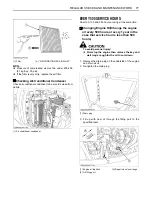
PURGING OF THE FUEL SYSTEM
1. Fill up the excavator with fuel.
2. Turn the starter key to the position "RUN".
3. The air in the fuel system will automatically be purged
within one minute.
A
If the purging was insufficient, the engine dies right
after starting. In this case repeat steps 2 to 3 again.
ADJUSTMENT OF TRACKS
C
To loosen the tracks, follow the following
procedure:
To avoid personal injury:
A
Do not loosen the grease nipple completely or
too quickly. Otherwise grease under high
pressure in the tension cylinder could squirt
out.
A
Do not crawl under the excavator.
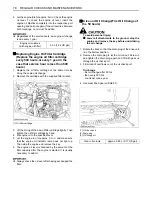
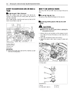
1. Loosen the bolts and remove the cover.
2. Using a socket wrench, loosen the grease nipple a few
turns.
3. When grease oozes out from the thread, rotate the
track and loosen the track in the lifted position (see
illustration).
After adjustment is completed:
Using the socket wrench, tighten the grease nipple.
Tightening torque must be between 98 to 108 N-m (72.3
to 79.7 ft-lbs).
A
If the tracks are too tight, wear is increased.
A
If the tracks are too loose, the track pads may collide
with the sprocket and wear is increased.
The track may dislocate or come off.
A
Clean the track after every use.
A
Should the track tension be high due to sticking mud,
lift the track with the help of the boom, arm and bucket,
idle the engine and remove mud from the track by
rotating it.
C
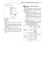
Tense the tracks as specified:
1. Loosen the bolt and remove the cover.
2. Apply grease to the grease nipple.
3.
Rubber Tracks
Tense the track in the lifted position, so that the
distance "A" (clearance between the track roller and
the inside surface of the track) see illustration, in this
case, if there is a seam mark "
" on the inside
surface of the track, the seam mark "
" is positioned
on the top center between the idler and the sprocket.
Steel Tracks
To check the track tension, the track must be lifted
from the ground as shown. The track tension is correct
if the clearance between the outer end of the track
roller and the track interior surface corresponds to the
dimension specified in the table below.
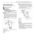
(1) Starter switch
(A) "STOP"
(B) "RUN"
(C) "START"
(1) Cover
(2) Bolt
(3) Grease nipple
(4) Grease gun
Summary of Contents for KX040-4
Page 10: ......
Page 18: ...SAFE OPERATION 8 6 DANGER WARNING AND CAUTION LABELS...
Page 19: ...9 SAFE OPERATION...
Page 20: ...SAFE OPERATION 10...
Page 21: ...11 SAFE OPERATION...
Page 22: ...SAFE OPERATION 12...
Page 23: ...13 SAFE OPERATION...
Page 69: ...45 EXCAVATOR OPERATION...
Page 125: ...101 LIFTING CAPACITY...
Page 126: ...102 LIFTING CAPACITY...

