background image

92

RECOMMENDED OILS

C

Maintenance Requirements when using BDF B0 through B5:
Follow the oil change intervals recommended by referring to the "MAINTENANCE" section. Extended oil change
intervals may result in premature wear or engine damage.

C

Maintenance Requirements when using BDF B6 through B20:
The maintenance interval for fuel related parts changes.
See the table below for the new maintenance interval.

C

Long Term Storage:

1. BDF easily deteriorates due to oxygen, water, heat and foreign substances.

Do not store B6 through B20 longer than 1 month and B5 longer than 3 months.

2. When using B6 through B20 and storing the machine longer than 1 month, drain the fuel from the tanks and replace

with light mineral oil diesel fuel.
Subsequently, run the engine at least 30 minutes to remove all of the Biodiesel from the fuel lines.

3. When using B5 fuel and storing machine longer than 3 months, drain the fuel from the tanks and replace with light

mineral oil diesel fuel.
Subsequently, run the engine at least 30 minutes to remove all of the Biodiesel from the fuel lines.

Items

Interval

Remarks

Fuel filter

Replace

every 250 hrs

Fuel hose

Check

every 100 hrs

Replace if any deterioration (crack, hardening, scar or 
deformation) or damage occurred.

Replace

every 1 year

Consult your local KUBOTA Dealer for this service.

Summary of Contents for KX033-4

Page 1: ...ATOR S MANUAL English U S A Code No RC488 8121 1 K X 0 3 3 4 PRINTED IN JAPAN KUBOTA Corporation 2016 READ AND SAVE THIS MANUAL MODEL 1BAAACGAP0010 eps 1BAAACGAP0020 eps 033 4 1BAAACGAP0020 1BAAACGAP0...

Page 2: ...uctures Society of Automotive Engineers USA Two Pattern Selection System Auto Idle API ASTM CECE DIN EN OSHA FRONT Hi ISO JIS L L min Lo MIL OPG Top Guard Level I rpm ROPS SAE TPSS AI IMPORTANT The en...

Page 3: ...gine Oil pressure Warning lamp Battery charge Indicator lamp Glow Working light switch Horn Wiper Washer switch Diesel Hydraulic fluid Gear oil Grease Fast Slow Excavator Overhead movement toward the...

Page 4: ...m It will give you long satisfactory service To obtain the best use of your excavator please read this manual carefully It will help you become familiar with the operation of the excavator and contain...

Page 5: ...16 When the Check up is Completed 18 Horn Switch 18 Light Switch 18 AUX Port Enable Switch 18 Auto Idle Control Switch 19 Throttle Potentiometer 19 Travel Speed Switch 19 CAB TYPE MACHINES 20 Wiper Wa...

Page 6: ...THE BOOM 35 OPERATION OF THE ARM 35 OPERATION OF THE BUCKET 36 UNIT SWING AND BOOM SWING OPERATION 36 Unit Swing Operation 36 Boom Swing Operation 36 AUXILIARY PORT OPERATION 37 Selecting the Action M...

Page 7: ...king Air Conditioner Condenser 69 EVERY 500 SERVICE HOURS 70 Changing Engine Oil Change the engine oil every 500 hours or every 1 year in the case that service hour is less than 500 hours 70 Replacing...

Page 8: ...unt of Refrigerant gas 77 OTHER ADJUSTMENTS AND REPLACEMENTS 79 PURGING OF THE FUEL SYSTEM 79 ADJUSTMENT OF TRACKS 79 Special Information when Using Rubber Tracks 80 CHANGING THE BUCKET 81 FUSES 81 Re...

Page 9: ...t belt when the machine is equipped with a ROPS OPG Top Guard Level I as this combination will reduce the risk of serious injury or death should the excavator be upset or falling objects occur Do not...

Page 10: ...perator must remain in the excavator seat during operation 13 Check levers pedals and all mechanical parts for correct adjustment and wear Replace worn or damaged parts immediately Check nuts and bolt...

Page 11: ...irection of the drive levers C Working 1 Do not operate or idle engine in a non ventilated area Carbon monoxide gas is colorless odorless and deadly If you experience the initial symptoms of low to mo...

Page 12: ...where you last saw them 2 Keep children out of the work area and under the watchful eye of another responsible adult 3 Be alert and shut your machine down if children enter the work area 4 Never carr...

Page 13: ...ot squirt out 1 Before doing work on the engine the exhaust system the radiator and the hydraulics let the excavator cool down sufficiently 2 Always turn off the engine when filling the fuel tank Avoi...

Page 14: ...ler where the machine was purchased or competent service shop The assembly must be done according to the KUBOTA work shop manual W S M for the product involved 17 When lifting the machine itself with...

Page 15: ...the machine Clean all electrical connections and tighten all electrical connections as necessary A Inspect the exhaust system daily for any signs of leakage Check for broken pipes and muffler and also...

Page 16: ...SAFE OPERATION 8 6 DANGER WARNING AND CAUTION LABELS...

Page 17: ...9 SAFE OPERATION...

Page 18: ...SAFE OPERATION 10...

Page 19: ...11 SAFE OPERATION...

Page 20: ...SAFE OPERATION 12...

Page 21: ...13 SAFE OPERATION...

Page 22: ...danger warning and caution labels with new labels from your KUBOTA dealer 4 If a component with danger warning and caution label s affixed is replaced with new part make sure new label s is are attach...

Page 23: ...hall however apply if the product has not been handled according to the instruction given in the Operator s Manual even it is within the warranty period The Product s described in this Operator s Manu...

Page 24: ...DEALER SERVICE 2 1 Engine serial No...

Page 25: ...M DI E4 US1 D1703 M DI E4 US2 D1703 M DI E4 US1 D1703 M DI E4 US2 Total displacement cc cu in 1647 100 5 Engine power SAE gross kW HP 18 5 24 8 SAE net kW HP 17 8 23 9 Rated speed rpm 2200 Low idle s...

Page 26: ...PICTED CONTENTS 1 Bucket cylinder 2 Arm 3 Bucket link 2 and 3 4 Bucket link 1 5 Bucket 6 Swing bracket 7 Arm cylinder 8 Canopy 9 Seat 10 Swing frame 11 Boom cylinder 12 Dozer cylinder 13 Dozer blade 1...

Page 27: ...hold switch Ref page Starter switch 7 Display selector switch 8 LCD 8 Fuel gauge Coolant temperature gauge Hour meter Engine tachometer Glow indicator Warninglamp 11 Information switch 11 User settin...

Page 28: ...om swing pedal 4 Drive lever right 5 Attachment control lever right 6 Dozer control lever Angle blade type 7 Drive pedal left 8 Drive pedal right Ref page Drive lever left 31 Attachment control lever...

Page 29: ...ELS in SAFE OPERATION section Inspect ROPS OPG Top Guard Level I for damage and if damage is found contact your KUBOTA dealer for repair CHECKING THE DEVICES BStarter Switch A STOP The key can be inse...

Page 30: ...Normal Operation C Fuel gauge To avoid personal injury or death A Before adding fuel be sure to stop the engine A Be sure to keep open flame away from the machine Otherwise a fire may result With the...

Page 31: ...to the buzzer sound for a rough estimate of the fill up progress C Coolant Temperature Gauge To avoid personal injury or death A Do not open the radiator cap during or just after operation Hot coolan...

Page 32: ...onscreen Also the following message shows up on the LCD and the engine automatically starts idling Acceleration is not operative If the above message appears take corrective measures referring to the...

Page 33: ...buzzer will beep See LIST OF SCREENS section for detail A Consult your local KUBOTA dealer from details concerning care and maintenance BLCD for Warning C Remaining fuel warning When the fuel level is...

Page 34: ...your local dealer for repair C Various error warnings If any components are detected to be in trouble the following message or similar appears onscreen See LIST OF SCREENS section For Example C Infor...

Page 35: ...e will be selected in this order Select an item to readjust Press the switch Switch 2 and the numeric setting will be smaller Press the switch Switch 3 and the numeric setting will be larger Hold down...

Page 36: ...when the battery is disconnected the following message appears onscreen Press the switch 5 to set the clock again A When the user setting switch Switch 1 is pressed on the clock setting screen the clo...

Page 37: ...switch 1 to make the menu appear onscreen 3 Press the switch 2 and 3 to select the log record Fix this choice with the switch Switch 5 4 Press the switch 5 to make the calendar appear onscreen Press t...

Page 38: ...iodic check interval has passed the message Periodic Check Passed shows up Immediately perform the specified servicing A The periodic check screen can also be preset to be made to disappear manually o...

Page 39: ...s or every 1 year 2 Hydraulic oil every 1000 hrs 3 Air filter element Outer element replace every 1000 hrs Inner element every 1000 hrs 4 Fuel filter every 500 hrs 5 Engine oil filter every 500 hrs or...

Page 40: ...the previous screen BHorn Switch BLight Switch When the starter switch is in position RUN the working light s and CAB light s will be switched on by pressing the switch C Night operation To avoid per...

Page 41: ...speed switch The buzzer beeps twice and the travel speed changes from low to high The symbol lights up 2 Press the travel speed switch again and the buzzer beeps once and the travel speed changes fro...

Page 42: ...r Washer Switch To engage the wiper turn on the switch for the wiper when the starter key is in the RUN position A further push on the switch will activate the washer system Even when the wiper switch...

Page 43: ...grip 2 Hold the grips tightly with both hands Pull the grip slightly upward and toward yourself to let the windshield slide inward 3 Pull the windshield all the way to the lock at the back of CAB 4 To...

Page 44: ...t allow water to enter the fresh air port while washing the excavator BAir Control Vent C Front air outlet The front air outlets can be independently adjusted as required To defrost the windshield rot...

Page 45: ...al to the COOL or an intermediate position to achieve the desired temperature level A Be sure to close the door while the air conditioner is ON otherwise you may overload the compressor C Cooling 1 Pr...

Page 46: ...r for more than 10 sec A If the engine does not start in 10 sec please wait 20 sec or more before attempting to restart STARTING THE ENGINE To avoid personal injury or death A The operator should not...

Page 47: ...rol lock lever is set at the LOCKED position A When the engine starts the meter may momentarily turn off and a beep may sound This is not a problem STARTING THE ENGINE UNDER COLD CONDITIONS To avoid p...

Page 48: ...9 Start the engine of the helping machine and let it run for a while Start the excavator with the low battery 10 Disconnect the jumper cables in the reverse sequence Steps 8 7 6 11 Replace the vent ca...

Page 49: ...g you scalded Make sure the radiator has cooled down enough before opening its cap If by any chance the coolant temperature rises close to or above the boiling point H on the water temperature gauge o...

Page 50: ...which can cause damage and shorten the life of many components Pay attention to the oil change intervals and complete them sooner than later See REGULAR CHECKS AND MAINTENANCE WORK section for more d...

Page 51: ...ands and body inside of the ROPS OPG Top Guard Level I protective A Do not touch the control levers and the pedals from outside the cab while the engine running BPilot Control Lock Lever To avoid pers...

Page 52: ...ont of the excavator A Use extra caution when traveling across a slope or working sideways on a slope A Recommended technique for working on a slope 1 Adjust the engine speed from idling to an interme...

Page 53: ...cavator forwards and vice versa The front of the excavator is the side where the dozer is located the drive sprocket is in the rear of the excavator TURNS To avoid personal injury or death A Do not ch...

Page 54: ...avator will turn in the direction of the arrow of the illustration below 2 Pull the left drive lever backward the excavator will turn in the direction of the arrow of the illustration below BSpin Turn...

Page 55: ...LING DOWNHILL TRAVELING PARKING ON A SLOPE To avoid personal injury or death A When the excavator is parked or left unattended on a slope be sure to put the bucket on the ground and place all control...

Page 56: ...to prevent accidental pattern change A Familiarize yourself with the pattern selected by operating slowly BPattern Change Position the pattern selector lever to the desired position 1 Pattern selecto...

Page 57: ...e oil warms up To lower the boom push the attachment control lever forward A When lowering the boom make sure that it does not hit the dozer and that the bucket teeth do not touch the dozer OPERATION...

Page 58: ...n the boom swing function is not used BUnit Swing Operation 1 Move the control lever to the left and the upper structure will turn to the left 2 Move the control lever to the right and the upper struc...

Page 59: ...een factory set to three action modes You can select one of them Up to five action modes can be preset Each time the AUX port enable switch switch 3 is pressed the action modes change over one after a...

Page 60: ...the switch 4 Display in AUX 1 modes BAUX Port Handling Procedure 1 Turn the starter key to the RUN position Let the engine warm up after start up for approx 10 minutes under no load conditions 2 Lower...

Page 61: ...low to fast movement of attachment Example If you move the AUX port knob halfway the attachment will move at approximately one half speed C One way hold Press the one way hold switch of the right atta...

Page 62: ...isplay appears onscreen 2 Press the switch 2 or 3 to select AUX Flow Ctrl Set and then press the switch 5 3 Each time the switch 5 is pressed the mode number changes Select your desired setting mode n...

Page 63: ...action mode is skipped even if selected Take an example of the following settings AUX standard icon for action mode 1 Breaker icon for action mode 2 Disable icon for actions modes 3 4 and 5 Each time...

Page 64: ...attachments might not be activated even when the bar level is still somewhat above the lowest position Or even when the bars of ports 1 and 2 are at the same level the same speed might not be achieve...

Page 65: ...Flow volume A When the AUX port is not used for a long period dirt particles can settle in the lower part of the AUX port lines When the plugs on the AUX port lines are removed to connect attachments...

Page 66: ...44 EXCAVATOR OPERATION...

Page 67: ...ydraulic system How to release pressure trapped in the AUX port 1 Perform the above operations of 1 to 4 2 Turn ON the AUX port enable switch 3 Make sure that the flow volume in all the AUX ports is n...

Page 68: ...tandard 0 marking Refer to Figure 1 A Do not work under the machine 1 Push the angle blade control switch to the right or left and the angle dozer is placed at an angle 2 For the right hand angle sett...

Page 69: ...fore mounting the equipment 1 way or 2 way circuit selection to avoid sudden movement of the equipment A Leaving the selection valve to 1 way circuit selection and attaching 2 way circuit equipment ma...

Page 70: ...the manner given in the points below This can cause damage to the machine Adhering soil can be shaken off when the bucket is being emptied by moving the bucket out to the maximum stroke of the cylinde...

Page 71: ...vehicle only with the arm completely pulled in A Do not jack up the machine using its boom to load or unload the excavator from the vehicle Doing this is dangerous Otherwise the CAB of the vehicle cou...

Page 72: ...ise the pilot control lock lever 9 Block the tracks with blocks and tie down the excavator B Towing the machine To avoid personal injury or death A When towing the excavator or pulling a load must be...

Page 73: ...e of the hook 5 The load must be lifted vertically from the ground 6 Do not enter the working area under suspended loads and do not move the load over people The load must only be moved in an area whe...

Page 74: ...in the following table Choose components having enough strength Excavator Weight With Angle blade steel tracks Steel wire 6X24 4 Lifting 1 Lift slowly and safely 2 Do not enter the excavator area when...

Page 75: ...66 replace every 500 hrs 72 13 Radiator hoses and clamps check every 200 hrs 67 replace every 2 years 76 14 Air filter element Outer element clean every 200 hrs 67 2 replace every 1000 hrs 75 2 Inner...

Page 76: ...0 hrs 66 replace every 500 hrs 72 13 Radiator hoses and clamps check every 200 hrs 67 replace every 2 years 76 14 Air filter element Outer element clean every 200 hrs 67 2 replace every 1000 hrs 75 2...

Page 77: ...egulation As the engine owner you are responsible for the performance of the required maintenance on the engine according to the above instruction Please see the warranty Statement in detail No Check...

Page 78: ...and close the engine hood Turn the key counterclockwise to lock the hood BOpening Closing of the Side Cover 1 Open the engine hood first 2 Raise the catch lever to unlock the side cover 3 Push the sid...

Page 79: ...nder the CAB door BCup Holder BWhere to store the Grease Gun CANOPY type The grease gun is located under the seat CAB type The grease gun is located under the CAB door BWhere to keep Operator s Manual...

Page 80: ...the recovery tank and fill up if necessary The coolant level should be between the marks FULL and LOW A Do not fill the recovery tank over the FULL marking A Do not fill with dirty or salty water BChe...

Page 81: ...the key before checking the oil level A Before filling oil wipe away all sand and dust from around the oil port Make sure to use an identical type of hydraulic fluid A The excavator has been filled w...

Page 82: ...ter hoses A Water leaks at joints or connecting points A Missing or damaged water hose protective sleeve or grommet A Loose mounting bolt damaged bracket A Do not touch the water hoses or the heater w...

Page 83: ...chine A Do not wash the excavator with the engine running Water could enter the air filter and damage the engine Make sure that the air filter is kept dry A Remove the mud before washing the machine B...

Page 84: ...marked grease fittings shown by arrows in the illustration below BGreasing Boom Swing Fulcrum Grease the marked grease fittings shown by arrows in the illustration below 1 Dozer cylinder boss 2 Dozer...

Page 85: ...el will settle down in the water separator When such foreign substances are deposited set the water separator handle to the OFF position Loosen the retainer ring and remove the cup Then dump water in...

Page 86: ...on or dismounting the battery be sure to turn off the engine and turn the starter switch to the OFF position A When removing the battery always disconnect the negative ground cable first When installi...

Page 87: ...rt time When using a boost charged battery it is necessary to recharge the battery as early as possible Failure to do this will shorten the battery s service life 3 The battery is charged if the indic...

Page 88: ...with a force of approx 58 8 to 68 6 N 6 to 7 kgf 13 2 to 15 4 lbf The belt tension is correct if it deflects about 9 to 11 mm 0 35 to 0 43 in When adjusting the fan belt loosen the lock nuts and turn...

Page 89: ...the central fitting 2 Grease at each 90 1 58 rad position of the swing frame Using the grease gun apply 5 shots at every position BInspection and Cleaning Air Filter Element Open the engine hood and...

Page 90: ...r 205 kPa 2 1 kgf 30 psi and the cartridge should be blown clean from the inside to the outside until the dust deposits are noticeably reduced A If the air suction is still inadequate or the color of...

Page 91: ...tion to the filter s normal air flow A Do not hit the filter If the filter becomes deformed dust may enter into the air conditioner which may cause damage and malfunction A Pressure of compressed air...

Page 92: ...side of the engine and drain all oil 2 Re tighten the drain plug 3 Fill up with new oil through the filling port to the specified level 4 Let the engine idle for approx 5 min Check the engine oil leve...

Page 93: ...the amount of the filter capacity after the engine is started It is usually necessary to add oil A Always check the oil level after having exchanged the filter BDrive unit Oil Change First Oil Change...

Page 94: ...ice hours To avoid personal injury or death A Remove the oil filter element only after the oil in the hydraulic tank has cooled down 1 Remove the cover of the hydraulic tank 2 Pull out the filter supp...

Page 95: ...ratch the O ring 7 Fit the case to the head cover 8 Let the engine run for approx 3 minutes 9 Check the oil level of hydraulic oil tank then tighten the oil filling plug BHydraulic Oil Change Includin...

Page 96: ...work 2 Use only the recommended oils mentioned in the operator s manual when changing or filling with oil 3 When filling up oil do not mix oils of different makes 2 Changing the return filter and oil...

Page 97: ...eplace damaged components immediately If a fuse blows out soon after having been replaced contact your nearest KUBOTA dealer Never use a fuse other than specified BChecking the Electrical Circuit Chec...

Page 98: ...from the engine use a container underneath the engine body to catch the fluids A Do not pour waste onto the grounds down a drain or into any water source A Also observe the relevant environmental prot...

Page 99: ...place the hoses and clamps if necessary See Checking Fuel Line and Intake Air Line in EVERY 200 SERVICE HOURS SERVICING AS REQUIRED BChecking Amount of Refrigerant gas To avoid personal injury or deat...

Page 100: ...our dealer to inspect and charge C Checking procedure 1 Run the air conditioner in the following conditions 2 Look into the sight glass to see if the refrigerant is flowing through its circuit A Charg...

Page 101: ...lustration After adjustment is completed Using the socket wrench tighten the grease fitting Tightening torque must be between 98 to 108 N m 72 3 to 79 7 ft lbs A If the tracks are too tight wear is in...

Page 102: ...sitioned incorrectly the tracks will be tensioned too loosely and a further readjustment will be necessary A Rotate the track after adjustment one to two times to check the tension A Additionally foll...

Page 103: ...e sure to wear eye protection a helmet and protective gloves A During attaching and detaching chippings and burns may occur at the bolts or bushings These may cause severe injuries A Never use your fi...

Page 104: ...5 Fuel Pump 13 Beacon 6 Electrical Outlet 14 Room Light 7 Engine Stop 15 ECU POWER 8 Meter B 16 Starter Signal 1 A C Controller B 12 Engine Stop 2 Blower Motor 13 Meter B 3 ECU AC 14 ECU B 4 Relay 15...

Page 105: ...circuits for trouble and then replace with a new compatible slow blow fuse CAB CANOPY C Replacement procedure 80 Amp Slow blow fuse 1 Disconnect the negative cord of the battery 2 Remove the slow blow...

Page 106: ...uns sluggishly in winter Pour hot water over the radiator Battery is almost dead insufficient compression Recharge battery Insufficient engine power Low fuel level Check fuel and add if necessary Clog...

Page 107: ...drive swing and dozer power is too low Hydraulic oil level too low Add oil Leakages of hoses and or joints Replace hose or joint Swing motor and front attachment does not work Pilot control lock lever...

Page 108: ...ween water and anti freeze A Use permanent anti freeze or long life coolant A Drain the coolant completely and clean the inside of the radiator then fill with the water and anti freeze mixture A The a...

Page 109: ...rive mechanisms under no load in order to circulate the hydraulic oil If the machine is stored for longer than 1 month do steps 1 and 2 once every month Periodic replacement of important component par...

Page 110: ...om cylinder Control valve Boom cylinder 2 5 Hydraulic hose Arm cylinder Control valve Pipe Boom 2 Pipe Boom Arm cylinder 2 6 Hydraulic hose Bucket cylinder Control valve Pipe Boom 2 Pipe Boom Bucket c...

Page 111: ...RECOMMENDED OILS 1 Before delivery the hydraulic oil used was Shell Tellus S2M46 2 Use engine oil API service classification CF CF 4 or better and SAE10W 30 3 Use SAE 90 API GL 4 GL 5 as drive unit o...

Page 112: ...E 10W 30 SAE 15W 40 0 to 25 32 to 77 SAE 20 or SAE 10W 30 SAE 15W 40 Below 0 32 SAE 10W or SAE 10W 30 SAE 15W 40 A Refer to the following table for the suitable API classification engine oil according...

Page 113: ...ng to current regulations based on the use of non BDF When using BDF the owner is advised to check applicable local and federal emission regulations and comply with all of them 2 BDF may cause restric...

Page 114: ...longer than 3 months 2 When using B6 through B20 and storing the machine longer than 1 month drain the fuel from the tanks and replace with light mineral oil diesel fuel Subsequently run the engine a...

Page 115: ...T A Above dimensions are based on the machine with rubber track A Specifications subject to change without notice mm in A B C D E F G H I J KX033 4 409 16 1 449 17 7 1550 61 0 4979 196 0 3529 139 0 32...

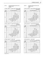
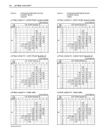
Page 116: ...are taken into consideration for the loads Machine conditions No bucket all others according to the standard regulations To avoid personal injury or death A No loads greater than those values mentione...

Page 117: ...95 LIFTING CAPACITY...

Page 118: ...96 LIFTING CAPACITY...

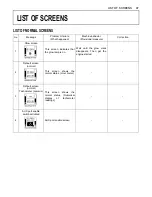
Page 119: ...n This screen indicates that the glow lamp is on Wait until the glow mark disappears Then get the engine started 2 Default screen normal This screen shows the normal status Hour meter 3 Default screen...

Page 120: ...ress Switch 5 to set the clock 2 Tilt up the lock lever This message indicates a procedural step Tilt up the pilot control lock lever This message disappears by tilting up the pilot control lock lever...

Page 121: ...l pressure error The engine lubricating system oil pressure is too low Stop the engine The engine may get burnt out Immediately stop the engine Immediately contact your local dealer 12 Overvoltage Thi...

Page 122: ...at and other problems cannot be detected Immediately contact your local dealer 16 Lock lever system error The lock lever system is in trouble The engine can run but the machine fails to move Immediate...

Page 123: ...AUX1 port system is in trouble The engine can get restarted and the machine can move but the AUX1 port system fails When the other systems than the AUX1 port system function the job can be continued I...

Reviews: