background image

english

6. Mechanical installation of the encoder

6.1 General mounting information

The encoder must not be disassembled or modified, either in total or in 

part.

No subsequent machining should be carried out on the shaft (grinding, 
sawing, drilling, etc.). This would impair the accuracy of the encoder and 
damage the bearings and shaft seals. We will be happy to accommodate 
your wishes.

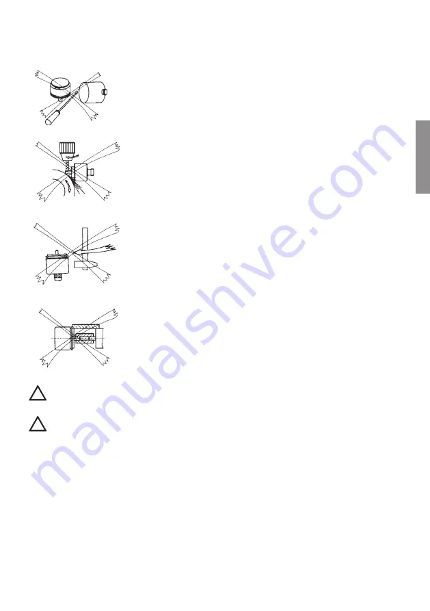
Never try to align the encoder using a hammer and never subject the en-
coder to impact shocks. - Do not subject the encoder shaft to loads (axial 
or radial) that are higher than the values given in the data sheet.

Do not rigidly connect the shafts and flanges of the encoder and driving 

device. Always use a coupling (between the drive shaft and the encoder 

shaft, or between the flange of the hollow shaft encoder and the flange of 

the drive).

  Couplings are to be designed and dimensioned, so that they meet the requirements of 

EN ISO 13849 or so that any possible breakage of the connection can be ruled out. 

  Depending on the specific use, the stator coupling/torque stop is subject to reduced wear. 

Please refer to chapter “Maintenance and Servicing”. 

 Unless otherwise specified, a friction coefficient of 0.14 is assumed for all screw connections.


Unless otherwise specified, a strength class of 8.8 is assumed for the screws.


The encoder cable must be routed free from any traction, so that no additional torque is applied 
to the encoder. The minimum bending radii of the cable are to be complied with. 

For the assembly, use only inspected/calibrated tooling that is subject to the quality system.

!

!

Buy: www.ValinOnline.com | Phone 844-385-3099 | Email: [email protected]

Summary of Contents for Sendix SIL 5814FS2

Page 1: ...s for Functional Safety Codeurs pour la s curit fonctionnelle Encoder per la sicurezza funzionale Encoder para la seguridad funcional Betriebsanleitung Operating Manual Instructions d utilisation Manu...

Page 2: ...dification without notice As a result of ongoing efforts to improve our products we reserve the right to make technical changes at any time to technical information contained in this document Warranty...

Page 3: ...nsmission 13 4 4 Recommended line termination and shielding 13 5 Operation in explosive areas 14 6 Mechanical installation of the encoder 15 6 1 General mounting information 15 6 2 Fastening 17 7 Elec...

Page 4: ...onnel also needs knowledge about the explosion protection concept 1 2 Symbols used Safety note A safety note informs you about potential or concrete oder potential dangers It is intended to protect yo...

Page 5: ...stness accuracy and long service life The IP protection rating of the encoders is either IP65 or IP67 depending on the shaft seal fitted As a result of the optical scanning of the singleturn and the m...

Page 6: ...ion 1 axial cable 1 m PVC 2 radial cable 1 m PVC 3 M23 connector 12 pin axial 4 M23 connector 12 pin radial e Code B SSI Binary C BiSS C Binary G SSI Gray f Resolution A 10 bit ST 12 bit MT 1 11 bit S...

Page 7: ...OS SLA SAR SDI SLI SLS SSR SSM SLP SCA 5863FS2 5873FS2 5883FS2 7053FS2 7063FS2 5814FS3 SS1 SS2 SOS SLA SAR SDI SLI SLS SSR SSM SIL3 EN 61800 5 2 PLe EN ISO 13849 1 5834FS3 7014FS3 5853FS3 SS1 SS2 SOS...

Page 8: ...ion class Danger pictogram Observe operating manual pictogram CE mark Signal Terminal assignment Wire colour Ex protection class only for Atex encoders Operating temperature range only for Atex encode...

Page 9: ...ion SAR Safe Acceleration Range SLI Safely Limited Increment SLP Safely Limited Position SCA Safe Cam 3 3 Safety Concept 3 3 1 Safe incremental encoder function In order to achieve safe incremental in...

Page 10: ...onnection of the encoder and the driving unit must be safety rated This concerns both the connection of the rotating element shafts connection and of the stationary section torque stop K bler supplies...

Page 11: ...lly i e A minus A gives the cosine B minus B gives the sine The signals A A B B have each an amplitude of 0 5 Vss with an offset of 2 5V against GND 4 1 1 Signals measured against GND 0 0 25 0 5 0 75...

Page 12: ...edge the current encoder data is stored in the buffer ready to be sent With the following rising clock pulse edg es data is transmitted bit by bit starting with the MSB Most Significant Bit The trans...

Page 13: ...ssed at any time The interface master provides for an unlimited number of subscribers the clock signal for simultane ously triggered actions For an example a typical RS422 link can support frame repet...

Page 14: ...explosive areas The explosion proof encoders Sendix SIL 70xxFSx have extended operation related requirements which are described in the separate installation instructions Z Z Data Data Clock Clock Bu...

Page 15: ...the encoder shaft or between the flange of the hollow shaft encoder and the flange of the drive Couplings are to be designed and dimensioned so that they meet the requirements of EN ISO 13849 or so t...

Page 16: ...der on the shaft Screw the stator coupling torque stop onto the flange of the drive without preload Tighten the clamping ring to the recommended torque without applying any preload to the stator coupl...

Page 17: ...ar offset 1 Clamping flange Flange type 1 with shaft type 2 represented with cable 1 3 x M3 6 0 24 deep 2 3 x M4 8 0 32 deep D 10f7 0 39 Flange type 1 with shaft type A represented with M23 connector...

Page 18: ...5883FSx Multiturn Abs a 67 2 64 67 2 64 70 5 2 78 Dimensions in mm inch 10 0 39 1 2 48 68 0 1 25 2 68 63 22 0 87 2 10 1 0 35 2 05 52 5 M 8 9 a 0 35 31 5 58 2 28 1 24 8 8 21 7 0 85 50 1 97 4 3 8 0 32 6...

Page 19: ...presented with M12 connector 1 SW 3 D 10H7 0 39 12H7 0 47 14H7 0 55 Flange with stator coupling and hollow shaft Flange type B represented with M23 connector 1 SW 3 2 for 4x M3 screws D 10H7 0 39 12H7...

Page 20: ...g screws with locking varnish or similar Dimensions in mm inch 8 12 entspricht Max zul ssige Toleranzen der Wellenverbindung Axialversatz 0 25 mm Radialversatz 0 20 mm Winkelversatz 1 8 12 a 56 2 2 56...

Page 21: ...hs For symmetric transmission e g compliant with RS422 max cable length 50 m Cable length with twisted pairs Connect or disconnect the mating connector only when the encoder is switched off Respect th...

Page 22: ...tive earth Shield PH Connector housing Shield Shield Cable shield A A Channel A Cosine signal B B Channel B Sine signal Top view of mating side male contact base M23 connector 12 pin M12 connector 8 p...

Page 23: ...connector 3 4 Signal 0V V C C D D SET PIN 1 2 3 4 5 6 7 Signal DIR A A B B PIN 8 9 10 11 12 PH V Encoder Power Supply V DC 0V Encoder ground GND 0 V C C Clock signal D D Data signal SET Set input DIR...

Page 24: ...on of the SSI BiSS interface If the wiring is incorrect no communication will be possible The data line must be terminated with a 120 ohm resistor Check the correct application of the sine cosine sign...

Page 25: ...not safety rated and serve only for the diagnostics 9 Maintenance and repairs The encoder is maintenance free In case of high loads e g due to high rotational speeds and revers ing operation the torqu...

Page 26: ...os interface Max frequency 3dB 400 kHz Short circuit resistance yes Pulse rate 1024 2048 ppr Offset 2 5 V 100 mV Offset difference A to B Max 25 mV Amplitude 1 Vss 10 Amplitude difference A to B Max 4...

Page 27: ...ing 1 Vss 0 3 V Characteristic values for the controller for Sendix SIL 58xxFS3 and 70xxFS3 Description Value Safety requirement SIL3 IEC 61508 compliant Error discovery rate DC 99 Error presumptions...

Page 28: ...s for mounting the encoders and the fastening elements have been complied with The shaft tolerances have been complied with so as to ensure the correct fit between the drive shaft and the encoder shaf...

Reviews: