background image

4


1. NOTICES

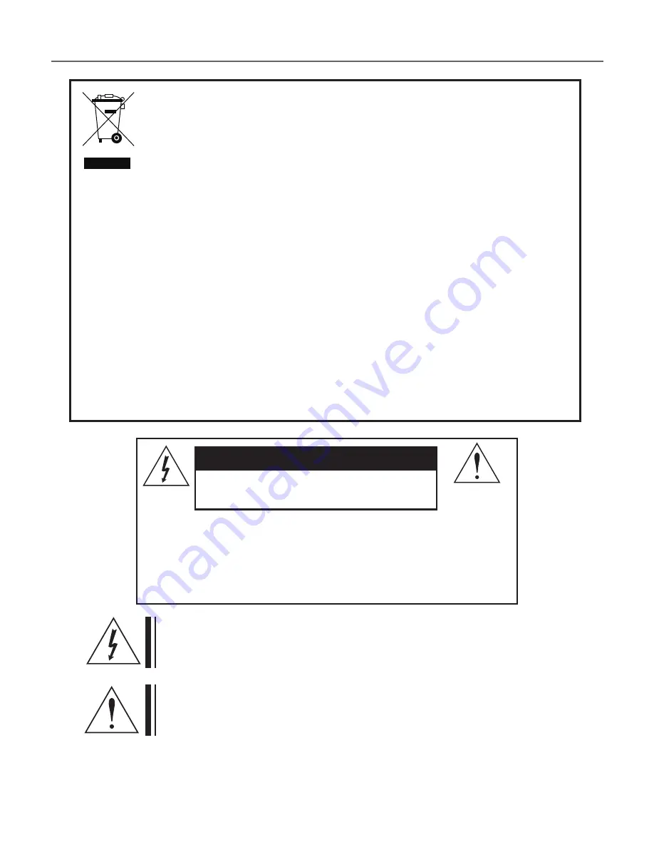
Correct Disposal of This Product

(Waste Electrical & Electronic Equipment)

(Applicable in the European Union and other European countries with 

separate collection systems)

This marking shown on the product or its literature indicates that it should 

not be disposed with other household wastes at the end of its working life. To 

prevent possible harm to the environment or human health from uncontrolled 

waste disposal, please separate this from other types of wastes and recycle it 

responsibly to promote the sustainable reuse of material resources. 

Household users should contact either the retailer where they purchased this 

product or their local government office for details of where and how to safely 

recycle the item.

Business users should contact their supplier and check the terms and 

conditions of the purchase contract.

This product should not be mixed with other commercial wastes for disposal.

CAUTION

RISK OF ELECTRIC SHOCK. 

DO NOT OPEN

CAUTION : TO REDUCE THE RISK OF ELECTRIC 

SHOCK, DO NOT REMOVE COVER(OR BACK). 
NO USER SERVICABLE PARTS INSIDE. 
REFER SERVICING TO QUALIFED SERVICE 
PERSONNEL.

This symbol is intended to alert the user to the presence of uninsulated 

"dangerous voltage" within the product's enclosure that may be of 

sufficient mangnitude to constitute a risk of electric shock to persons.

This symbol is intended to alert the user to the presence of important 

operating and maintenance(servicing) instruction in the literature 

accompanying the appliance.

Summary of Contents for TBN6302

Page 1: ...FULL HD TVI Box Camera OPERATION MANUAL Thank you for choosing our high quality camera Before attempting to connect operate this unit please read and follow these instructions M250 TBN6302 001...

Page 2: ...MENU STRUCTURE TVI UTC UP THE COAX 1 2 3 4 5 6 7 8 9 10 11 These servicing instructions are for use by qualified service personnel only To reduce the risk of electric shock do not perform any servici...

Page 3: ...FCC regulations Operation is subject to the following two conditions 1 This device may not cause harmful interference 2 This device may receive interference that can cause affect the opration of this...

Page 4: ...or their local government office for details of where and how to safely recycle the item Business users should contact their supplier and check the terms and conditions of the purchase contract This...

Page 5: ...rovided plug does not fit your outlet consult an electrician 10 Ensure that nothing rests on your equipment s cables and that the cables are not located where they can be stepped on tripped over or pi...

Page 6: ...t Video Interface Output HD TVI is suitable for long reach transmission over single coaxial cable Transmission Distance 300 m Color Max Transmission Distance 500 m Service video output for convenient...

Page 7: ...7 4 COMPONENTS DSP COLOR CAMERa c mount adaptor ring operation manual...

Page 8: ...RIS JACK TRIPOD MOUNTING HOLE 1 4 20 UNC BACK MENU BUTTON UP BUTTON DOWN BUTTON LEFT BUTTON RIGHT BUTTON POWER LED The LED turns on when power is supplied HD TVI OUTPUT JACK VIDEO OUT JACK Used to con...

Page 9: ...by screwing it in clockwise 5 Insert the connection plug that is connected to the auto iris lens cable into the auto iris lens connector located on the side of the camera C mount lens 10 mm or less CS...

Page 10: ...10 6 INSTALLATION Installation of C Mount Lenses Installation of CS Mount Lens 10 CS MOUNT ADAPTOR RING C MOUNT ADAPTOR RING CS MOUNT ADAPTOR RING...

Page 11: ...NNECTION 12VDC 24VAC 12VDC HD TVI VIDEO INPUT TV MONITOR 24VAC 12VDC REGULATED POWER SUPPLY HD TVI OUTPUT BNC FEMALE VIDEO OUTPUT HD TVI VIDEO INPUT TV MONITOR 12VDC REGULATED POWER SUPPLY HD TVI OUTP...

Page 12: ...12 8 DIMENSIONS Unit mm 58 58 110 4 109 1 4 20 UNC...

Page 13: ...CR Mechanism OSD Built in 3DNR Off On Level Adjustable WDR Off On Level Adjustable Motion Detection Off On Privacy Mask Off On for 8 selectable zones Lens Shading Correction Off On with adjustable lev...

Page 14: ...CE MODE AUTO PUSH LOCK MANUAL AUTO EXT PUSH AUTO PUSH CHROMA 1 20 RED GAIN 0 20 BLUE GAIN 0 20 INITIAL RETURN WDR BLC MODE OFF BLC HLC WDR LEVEL 1 10 BLC POSITION BLC SIZE HLC COLOR BLACK D GRAY L GRA...

Page 15: ...SIZE ZONE COLOR BLACK WHITE YELLOW C Y A N G R E E N MAGENTA RED BLUE TRANSPARENCY 100 75 50 25 0 INITIAL RETURN MOTION OFF ON SENSITIVITY LOW MID HIGH DISPLAY MARK AREA INITIAL RETURN SYSTEM LANGUAGE...

Page 16: ...d DVR setting method DVR maker HIKVISION STEP 1 Enter HIKVISION DVR menu Select Camera icon STEP 2 Select PTZ item Select PTZ setting icon STEP 3 Select PELCO C Coaxitron STEP 4 Exit menu Please click...

Reviews: