

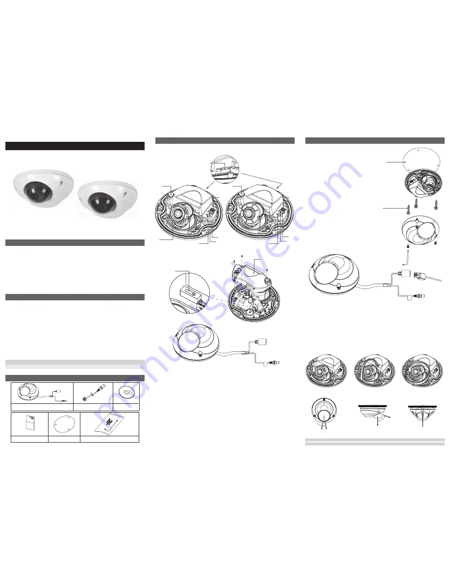
3. Product Description
Description and Function
LED Type
Standard Type
1. Infrared LED –
These LEDs emit infrared radiations.
2. Reset Button –
Press the reset switch for more than 10 seconds,
the restore the camera to the function default settings.
3. Service Video Connector –
Outputs video to the monitor.
4. Power LED –
Power ON when DC Power is Connected.
5. Status LED
6. MIC
7. Micro SD Card Socket
.
8. NTSC / PAL Toggle Switch.
9. Power Input(DC12V) –
Connects to DC 12V power.
10. Network Connector –
The Network Camera connects to the network via a standard network cable, and
automatically detects the speed of the local network segment
(10BaseT/100BaseTX Ethernet). PoE Supported
M173-LD(N)Di45-001
Megapixel Network Camera
Installation Guide
Table of Contents
1.INTRODUCTION
2.PACKAGE CONTENTS
3.PRODUCT DESCRIPTION
4.HARDWARE INSTALLATION
5.IP ADDRESS ASSIGNMENT
6.PRODUCT SPECIFICATIONS
1. Introduction
IP Dome Camera Installation Guide
This installation guide provides instructions for installing the Network Camera on your
network. For all other aspects of using the product, please see the User’s Manual,
available on the CD included in this package.
Installation Steps
1. Check the package contents against the list below.
2. Read the Product description.
3. Install the hardware.
4. Set an IP address.
5. Set the admin and user ID and password. (See User’s Manual)
6. Product Specifications
Important!
This product must be used in compliance with local laws and regulations.
2. Package Contents
Network Camera
Video Output Test Cable
Software CD
Installation Guide
Template
Screws / L-Wrench
4. Hardware Installation
IP cameras are designed to be installed using a template as shown below.
1. Template – To mount the camera.
2. Screws(3ea) – To secure the camera to the template.
Connection
1. Connect the camera to the network using a UTP cable (CAT.5). Power can be supplied via
the network cable (PoE)
2. Connect DC 12V to the power terminal. This is not necessary if the Network Camera is
connected to a PoE hub or midspan.
3. Check that the indicator LEDs indicate the correct conditions.
4. Connect the analog monitor to the service video connector for adjusting focus, then press and quickly
release the reset switch for focus assistant mode.
Then you can select normal view or focus view mode using the reset switch.
Caution: When you use focus assistant mode, “Focus View” mode is recommended for more exact focus.
Caution: Focus assistant mode will be automatically exited after 3 minutes for normal operation.
3-Axis Gimbal
Pan Rotation
Pan: ±15°
Tilt:
LED Type: 0~75°
Standard Type: 0~90°
Rotate: ±180°
Horizontal Rotation
Tilt Rotation
CAUTION
panning(Pan + Horizontal) the bracket in excess of 1 rotations in one direction may cause damage to the cable.
CAUTION
With certain wide-angle lenses, the upper part of the image may be obscured when the tilt angle exceeds 80°
➊
➌
➌
➏
➏
➋
➋
➍
➍
➒
➓
➐
➎
➎
❷
❶
Cover Open
L-Wrench
➑


