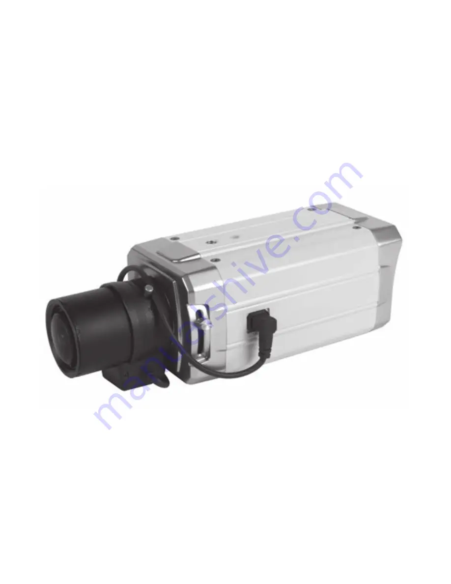
background image

HIGH RESOLUTION 

WDR COLOR CAMERA

O P E R AT I O N   M A N U A L

T h a n k   y o u   f o r   c h o o s i n g   o u r   h i g h   q u a l i t y   c a m e r a .  
B e f o r e   a t t e m p t i n g   t o   c o n n e c t   o r   o p e r a t e ,   p l e a s e   r e a d   a n d   f o l l o w  
t h e s e   i n s t r u c t i o n s .

M096-WDR7000-001

Summary of Contents for KPC-WDR7000NU

Page 1: ...HIGH RESOLUTION WDR COLOR CAMERA OPERATION MANUAL Thank you for choosing our high quality camera Before attempting to connect or operate please read and follow these instructions M096 WDR7000 001...

Page 2: ...CONTENTS 1 CAUTIONS 2 FEATURES 3 COMPONENTS 4 NAME AND FUNCTION 5 INSTALLATION 6 DIMENSIONS 7 SPECIFICATION 8 OSD MANUAL 2...

Page 3: ...CONTENTS 1 CAUTIONS 2 FEATURES 3 COMPONENTS 4 NAME AND FUNCTION 5 INSTALLATION 6 DIMENSIONS 7 SPECIFICATION 8 OSD MANUAL 2...

Page 4: ...se radio interference in which case the user may be required to take adequate measures Caution Any changes or modifications in construction of this device which are not expressly approved by the party...

Page 5: ...onment or human health from uncontrolled waste disposal please separate this from other types of wastes and recycle it responsibly to promote the sustainable reuse of material resources This product s...

Page 6: ...hinese Russian Spanish German Digital slow shutter 3DNR Privacy Zone 15Zone 3x Digital Zoom Motion Detect Face Detection DC12V DC12V AC24V Dual Voltage RS 485 Communication True Day Night With ICR Mec...

Page 7: ...3 COMPONENTS HIGH PERFORMANCE WDR COLOR CAMERA AUTO IRIS LENS CONNECTION PLUG C MOUNT ADAPTOR RING OPERATION MANUAL 6 NOTE PLEASE REMOVE PROTECTION FILM Class 2 Only...

Page 8: ...4 NAME AND FUNCTION FRONT 7 TRIPOD MOUNTING HOLE 1 4 20 UNC AUTO IRIS JACK MOUNT COVER C MOUNT ADAPTOR RING TRIPOD MOUNTING HOLE 1 4 20 UNC BACK FOCUS CONTROL LEVER...

Page 9: ...RS 485 Communication B Motion detection feature is to generate an alarm whenever movement occurs in the video When Motion Mode is set ON on the OSD menu of the camera Normal status 0V Motion detected...

Page 10: ...E Please keep the lens clean Any foreign objects and Finger marks on the lens can cause inferior image quality in low light level conditions When using an auto iris lens 1 Please peel off about 8mm of...

Page 11: ...CONNECTOR 1 Video auto iris lens Pin 1 Power source DC 12V Pin 2 N C Not used Pin 3 Video signal Pin 4 Shield GND Ground 2 DC auto iris lens Pin 1 DAMP CTL Pin 2 DAMP CLT Pin 3 DRV Pin 4 DRV GND 4 Ple...

Page 12: ...he auto iris lens cable into the auto lens connector which is located on the side of the camera 11 C mount lens 10mm or less CS mount lens 5mm or less NOTE Use the lens under the specification as show...

Page 13: ...5 INSTALLATION Installation of C Mount Lens Installation of CS Mount Lens 12 C MOUNT ADAPTOR RING...

Page 14: ...l supplied with the instrument Only connect the cable when the power is turned off Set the 75 Hi Z selection switch as shown below if you have an intermediate device 13 DC12V REGULATED POWER SUPPLY BN...

Page 15: ...14 6 DIMENSIONS Unit mm 143 5 C Mount 138 5 CS Mount AUTO IRIS JACK TRIPOD MOUNTING HOLE C MOUNT ADAPTOR RING 72 5 66 TRIPOD MOUNTING HOLE 1 4 20 UNC Depth 5...

Page 16: ...ue Day Night with ICR Mechanism COLOR BW AUTO EXT Motion Detection ON OFF Level adjustable Area adjustment Face Detection ON OFF Level adjustable Area adjustment Privacy Masking 15 Zones Area adjustme...

Page 17: ...AULT EXIT LENS LENS TYPE DC LEVEL 08 INITIAL RETURN EXPOSURE SHUTTER 1 60 FLICKERLESS OFF AGC MID DSS 10x INITIAL RETURN WHITE BALANCE WB MODE ATW RED CONT BLUE CONT PUSH CONT INITIAL RETURN WDR BLC W...

Page 18: ...LOR DWELL TIME D N LEVEL N D LEVEL INITIAL RETURN IMAGE REVERSE NORMAL DNR OFF DNR LEVEL 4 SHARPNESS 10 FREEZE OFF D ZOOM 1 0x INITIAL RETURN SPECIAL CAM TITLE LANGUAGE ENGLISH COMM ADJ PRIVACY MOTION...

Page 19: ...18 8 OSD MANUAL LENS MENU STRUCTURE EXPOSURE MENU STRUCTURE...

Page 20: ...19 8 OSD MANUAL WHITE BALANCE MENU STRUCTURE WDR MENU STRUCTURE...

Page 21: ...20 8 OSD MANUAL DAY NIGHT MENU STRUCTURE IMAGE MENU STRUCTURE...

Page 22: ...21 8 OSD MANUAL SPECIAL CAM TITLE SPECIAL LANGUAGE...

Page 23: ...22 8 OSD MANUAL SPECIAL COMM ADJ SPECIAL PRIVACY...

Page 24: ...23 8 OSD MANUAL SPECIAL MOTION DET SPECIAL DISPLAY...

Page 25: ...able user to set up the function of SHUTTER FLICKERLESS AGC DSS Set up using LEFT RIGHT KEY at each menu SHUTTER Enable user to set up the Shutter Speed 1 60 50 1 100 120 1 250 1 500 1 1K 1 2K 1 4K 1...

Page 26: ...ED GAIN BLUE CONT In the USER setting of WB MODE enable user to set the BLUE GAIN PUSH AUTO In the PUSH LOCK setting of WB MODE enable user to fix the White Balance in camera setting INITIAL Enable us...

Page 27: ...to COLOR BW automatically by luminace element on Screen EXT Enable user to convert to COLOR BW by signal of the exterior input Low input signal COLOR High input signal BW DWELL TIME In D N MODE AUTO...

Page 28: ...ise by using time based filtering DNR LEVEL Enable user to set level 0 15 steps SHARPNESS Enable user to control the image sharpness 0 15steps FREEZE Enable user to freeze the image D ZOOM Digital Zoo...

Page 29: ...ing LEFT RIGHT KEY in LOCATION By using UP DOWN LEFT RIGHT KEY enable user to choose any letters in LOCATION and then get back to previous step Enable user to finish words choice and position by using...

Page 30: ...ble user to set up positions from 0 to 14 MASK Enable user to set up screen output of chosen position V START Mask Vertical start position V END Mask Vertical end position H START Mask Horizontal star...

Page 31: ...E MOTION FACE CAM ID Enable user to set up output on Camera ID screen CAM TITLE Enable user to set up output in fixed CAM TITLE MOTION DETECT Enable user to set up out put of MOTION on the screen as M...

Page 32: ...31 8 Communication Protocol Pelco D Protocol Commands Most widely used Commands TELE UP KEY WIDE DOWN KEY NEAR LEFT KEY FAR RIGHT KEY MENU MENU KEY...

Page 33: ...se radio interference in which case the user may be required to take adequate measures Caution Any changes or modifications in construction of this device which are not expressly approved by the party...

Page 34: ...onment or human health from uncontrolled waste disposal please separate this from other types of wastes and recycle it responsibly to promote the sustainable reuse of material resources This product s...

Page 35: ...hinese Russian Spanish German Digital slow shutter 3DNR Privacy Zone 15Zone 3x Digital Zoom Motion Detect Face Detection DC12V DC12V AC24V Dual Voltage RS 485 Communication True Day Night With ICR Mec...

Page 36: ...3 COMPONENTS HIGH PERFORMANCE WDR COLOR CAMERA AUTO IRIS LENS CONNECTION PLUG C MOUNT ADAPTOR RING OPERATION MANUAL 6 NOTE PLEASE REMOVE PROTECTION FILM Class 2 Only...

Page 37: ...4 NAME AND FUNCTION FRONT 7 TRIPOD MOUNTING HOLE 1 4 20 UNC AUTO IRIS JACK MOUNT COVER C MOUNT ADAPTOR RING TRIPOD MOUNTING HOLE 1 4 20 UNC BACK FOCUS CONTROL LEVER...

Page 38: ...RS 485 Communication B Motion detection feature is to generate an alarm whenever movement occurs in the video When Motion Mode is set ON on the OSD menu of the camera Normal status 0V Motion detected...

Page 39: ...E Please keep the lens clean Any foreign objects and Finger marks on the lens can cause inferior image quality in low light level conditions When using an auto iris lens 1 Please peel off about 8mm of...

Page 40: ...CONNECTOR 1 Video auto iris lens Pin 1 Power source DC 12V Pin 2 N C Not used Pin 3 Video signal Pin 4 Shield GND Ground 2 DC auto iris lens Pin 1 DAMP CTL Pin 2 DAMP CLT Pin 3 DRV Pin 4 DRV GND 4 Ple...

Page 41: ...he auto iris lens cable into the auto lens connector which is located on the side of the camera 11 C mount lens 10mm or less CS mount lens 5mm or less NOTE Use the lens under the specification as show...

Page 42: ...5 INSTALLATION Installation of C Mount Lens Installation of CS Mount Lens 12 C MOUNT ADAPTOR RING...

Page 43: ...l supplied with the instrument Only connect the cable when the power is turned off Set the 75 Hi Z selection switch as shown below if you have an intermediate device 13 DC12V REGULATED POWER SUPPLY BN...

Page 44: ...14 6 DIMENSIONS Unit mm 143 5 C Mount 138 5 CS Mount AUTO IRIS JACK TRIPOD MOUNTING HOLE C MOUNT ADAPTOR RING 72 5 66 TRIPOD MOUNTING HOLE 1 4 20 UNC Depth 5...

Page 45: ...ue Day Night with ICR Mechanism COLOR BW AUTO EXT Motion Detection ON OFF Level adjustable Area adjustment Face Detection ON OFF Level adjustable Area adjustment Privacy Masking 15 Zones Area adjustme...

Page 46: ...AULT EXIT LENS LENS TYPE DC LEVEL 08 INITIAL RETURN EXPOSURE SHUTTER 1 60 FLICKERLESS OFF AGC MID DSS 10x INITIAL RETURN WHITE BALANCE WB MODE ATW RED CONT BLUE CONT PUSH CONT INITIAL RETURN WDR BLC W...

Page 47: ...LOR DWELL TIME D N LEVEL N D LEVEL INITIAL RETURN IMAGE REVERSE NORMAL DNR OFF DNR LEVEL 4 SHARPNESS 10 FREEZE OFF D ZOOM 1 0x INITIAL RETURN SPECIAL CAM TITLE LANGUAGE ENGLISH COMM ADJ PRIVACY MOTION...

Page 48: ...18 8 OSD MANUAL LENS MENU STRUCTURE EXPOSURE MENU STRUCTURE...

Page 49: ...19 8 OSD MANUAL WHITE BALANCE MENU STRUCTURE WDR MENU STRUCTURE...

Page 50: ...20 8 OSD MANUAL DAY NIGHT MENU STRUCTURE IMAGE MENU STRUCTURE...

Page 51: ...21 8 OSD MANUAL SPECIAL CAM TITLE SPECIAL LANGUAGE...

Page 52: ...22 8 OSD MANUAL SPECIAL COMM ADJ SPECIAL PRIVACY...

Page 53: ...23 8 OSD MANUAL SPECIAL MOTION DET SPECIAL DISPLAY...

Page 54: ...able user to set up the function of SHUTTER FLICKERLESS AGC DSS Set up using LEFT RIGHT KEY at each menu SHUTTER Enable user to set up the Shutter Speed 1 60 50 1 100 120 1 250 1 500 1 1K 1 2K 1 4K 1...

Page 55: ...ED GAIN BLUE CONT In the USER setting of WB MODE enable user to set the BLUE GAIN PUSH AUTO In the PUSH LOCK setting of WB MODE enable user to fix the White Balance in camera setting INITIAL Enable us...

Page 56: ...to COLOR BW automatically by luminace element on Screen EXT Enable user to convert to COLOR BW by signal of the exterior input Low input signal COLOR High input signal BW DWELL TIME In D N MODE AUTO...

Page 57: ...ise by using time based filtering DNR LEVEL Enable user to set level 0 15 steps SHARPNESS Enable user to control the image sharpness 0 15steps FREEZE Enable user to freeze the image D ZOOM Digital Zoo...

Page 58: ...ing LEFT RIGHT KEY in LOCATION By using UP DOWN LEFT RIGHT KEY enable user to choose any letters in LOCATION and then get back to previous step Enable user to finish words choice and position by using...

Page 59: ...ble user to set up positions from 0 to 14 MASK Enable user to set up screen output of chosen position V START Mask Vertical start position V END Mask Vertical end position H START Mask Horizontal star...

Page 60: ...E MOTION FACE CAM ID Enable user to set up output on Camera ID screen CAM TITLE Enable user to set up output in fixed CAM TITLE MOTION DETECT Enable user to set up out put of MOTION on the screen as M...

Page 61: ...31 8 Communication Protocol Pelco D Protocol Commands Most widely used Commands TELE UP KEY WIDE DOWN KEY NEAR LEFT KEY FAR RIGHT KEY MENU MENU KEY...

Reviews: