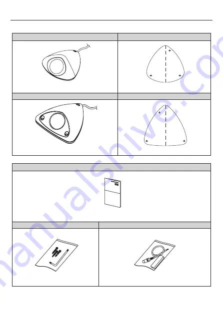
3. EQUIPMENT AND ACCESSORIES
Plastic Dome Type
Mount Guide (Plastic Dome Type)
Vandal Dome Type
Mount Guide (Vandal Dome Type)
Manual
Screws(3ea) / L-Wrench
Service Video Output Test Cable / Fixed Tape
6
Page 1: ...WDR FLAT DOME CAMERA OPERATION MANUAL Thank you for choosing our high quality camera Before attempting to connect operate this unit please read and follow these instructions M150 LD40LV40 001 VANDAL D...
Page 2: ...ng instructions unless you are qualified to do so Use Class 2 Power Supply Only CAUTION 2 CONTENTS 1 CAUTIONS 2 IMPORTANT SAFETY INSTRUCTION 3 EQUIPMENT AND ACCESSORIES 4 CAMERA COMPONENT DESCRIPTIONS...
Page 3: ...e radio interference in which case the user may be required to take adequate measures Caution Any changes or modifications in construction of this devices which are not expressly approved by the party...
Page 4: ...overnment office for details of where and how they can take item for environmentally safe recycling Business users should contact their supplier and check the terms and conditions of the purchase cont...
Page 5: ...o your outlet consult an electrician for replacement of the obsolete outlet 10 Protect the power cord from being walked on or pinched particularly at plugs convenience receptacles and the point where...
Page 6: ...3 EQUIPMENT AND ACCESSORIES Plastic Dome Type Mount Guide Plastic Dome Type Vandal Dome Type Mount Guide Vandal Dome Type Manual Screws 3ea L Wrench Service Video Output Test Cable Fixed Tape 6...
Page 7: ...4 CAMERA COMPONENT DESCRIPTIONS 7 NO PART NAME 1 Top Case 2 Dome Cover 3 Dome Bracket 4 Dome Ass y 5 Cable 6 Main PCB 7 OSD Controller 8 Bottom Case 1 2 3 4 5 6 8 7 Plastic Dome Type...
Page 8: ...CAMERA COMPONENT DESCRIPTIONS 8 1 2 3 4 7 6 9 8 5 Vandal Dome Type NO PART NAME 1 Top Case 2 Dome Cover 3 Case Rubber 4 Dome Bracket 5 Dome Ass y 6 Main PCB 7 Safety Wire 8 OSD Controller 9 Bottom Cas...
Page 9: ...ingly using the OSD controller 4 After the LENS SETTING is completed install the TOP COVER 9 TAPPING SCREW 4 x 20L 3EA TOP HOUSING Assembly direction TOP HOUSING Separation Direction ASSEMBLY HOOK 2 p...
Page 10: ...e SETTINGS accordingly using the OSD controller 5 After the LENS SETTING is completed install the TOP COVER 10 CASE RUBBER Before assembling the top housing Be sure the Rubber correctly positioned M4...
Page 11: ...e glue up the end of cable to keep it stable in order to protect the camera from the humidity problems DC12V AC24V DC12V CAMERA BNC FEMALE DC12V AC24V POWER SUPPLY DC12V AC24V TERMINAL BLOCK VIDEO IN...
Page 12: ...6 DIMENSIONS Unit mm 12 119 119 42 134 139 49 Plastic Dome Type Vandal Dome Type...
Page 13: ...HLC ON AUTO OFF Level adjustable AGC OFF 6 36dB DNR 2D 3D ON OFF Level adjustable Image Function Image reverse Normal Flip Freeze Contrast Sharpness Day Night COLOR BW AUTO DIGITAL D N Motion Detecti...
Page 14: ...ONLY 1 50 PAL 1 60 NTSC 1 100 NTSC 1 120 PAL 1 250 1 500 1 1000 1 2000 1 4000 1 10000 MODE SLOW ONLY 2 4 8 16 32 64 128 256 AGC 6 12 18 24 30 36 42 44 8 RETURN WHITE BALANCE ATW SPEED 0 255 DELAY CNT...
Page 15: ...URN IMAGE HV FLIP OFF ON FREEZE OFF ON EZOOM 1 0x 3 0x CONTRAST 0 63 SHARPNESS 0 15 RETURN SPECIAL CAMERA TITLE OFF ON DISPLAY THE TITLE EDITING MENU RETURN LANGUAGE ENGLISH ESPA OL DEUTSCH FRANCAIS P...
Page 16: ......