background image

6. INSTALLATION

10

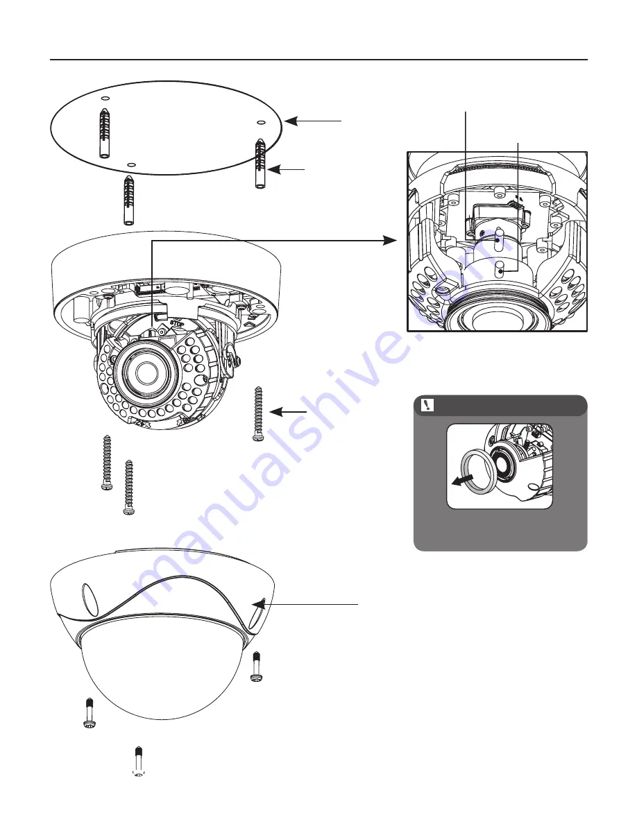
Cover Screws(3ea): 
are “captive and will 
normally be retained in 
cover. They are shown 
here for illustration 
purposes.

Screws(3ea)

Plastic Anchors
(3ea)

Template

Lens Zoom Knob

Lens Focus Knob

When using the camera 

without LED take off the rubber.

N O T E

Summary of Contents for KPC-HDV122

Page 1: ...Digital Video Vandal Dome Camera OPERATION MANUAL Thank you for choosing our high quality camera Before attempting to connect operate this unit please read and follow these instructions M160 HD N V12...

Page 2: ...use by qualified service personnel only To reduce the risk of electric shock do not perform any servicing other than that contained in the operating instructions unless you are qualified to do so Use...

Page 3: ...1 CAUTIONS 2 IMPORTANT SAFETY INSTRUCTION 3 FEATURES 4 EQUIPMENT AND ACCESSORIES 5 CAMERA COMPONENT DESCRIPTIONS 6 INSTALLATION 7 DIMENSIONS 8 SPECIFICATION 9 OSD MANUAL Menu structure Function Descr...

Page 4: ...radio interference in which case the user may be required to take adequate measures Caution Any changes or modifications in construction of this devices which are not expressly approved by the party r...

Page 5: ...onment or human health from uncontrolled waste disposal please separate this from other types of wastes and recycle it responsibly to promote the sustainable reuse of material resources This product s...

Page 6: ...o your outlet consult an electrician for replacement of the obsolete outlet 10 Protect the power cord from being walked on or pinched particularly at plugs convenience receptacles and the point where...

Page 7: ...u for setup and configuration Lens Control DC Iris 30 Long Life IR illuminations for 0 Lux viewing performance and range to 20m 65 feet LED type model only Provides True Day Night Capability with Moto...

Page 8: ...4 EQUIPMENT AND ACCESSORIES Camera Template Manual Screws Plastic anchors Wrench Service Video Output Test Cable When using Wall Mount Bracket 8...

Page 9: ...MPONENT DESCRIPTIONS LED Type Standard Type 9 CONTROL FUNCTION OSD JOYSTICK LEFT UP RIGHT DOWN MENU OSD Joystick Cooling Fan Cooling Fan Option Service Video Connector Service Video Connector OSD Joys...

Page 10: ...3ea are captive and will normally be retained in cover They are shown here for illustration purposes Screws 3ea Plastic Anchors 3ea Template Lens Zoom Knob Lens Focus Knob When using the camera withou...

Page 11: ...keep it stable in order to protect the camera from the humidity problems MONITOR BNC FEMALE VIDEO HD SDI IN DC 12V AC 24V POWER SUPPLY SDI RECEIVER DISPLAY DEVICE RS485 RS485 MONITOR BNC FEMALE VIDEO...

Page 12: ...7 DIMENSIONS Unit mm 12 112 8 151 107 123 4 71 5 124...

Page 13: ...xt PUSH MANUAL Lens Control DC IRIS OSD Menu Yes Power Consumption W O Heater DC12V DC 12V 10 Max 200mA DUAL DC 12V 10 Max 260mA AC 24V 10 Max 3 7W Heater Option DC12V DC 12V 10 Max 1 05A DUAL DC 12V...

Page 14: ...0 10 BASE FREQ 60Hz 50Hz RESET DATA BACK DEF RETURN BACK EXIT WHITE BALANCE WB MODE AUTO AUTOext PUSH MANUAL COLORTEMP LOW MIDDLE HIGH R GAIN 0 20 B GAIN 0 20 RETURN BACK EXIT SATURATION 0 20 RESET D...

Page 15: ...OLOR BLK WHI YEL CYN GRN MAG RED BLU RESET DATA BACK DEF RETURN BACK EXIT PATTERN OFF 0 1 DISPLAY INFO CAMERA ID NUM OFF ON RETURN BACK EXIT RESET DATA BACK DEF RETURN BACK EXIT SYSTEM COMM ADJUST CAM...

Page 16: ...SHUTTER Select shutter speed control type LEVEL Adjust shutter speed at manual shutter mode DSS Adjust digital slow shutter control level AGC Adjust max gain level for brightness control BASE FREQ Se...

Page 17: ...ronment setting Make video image act in color B W Fix to mode at night environment setting Make video image act in B W D N DETECT Select AGC or CDS control for TDN auto control DELAY Delay time for ch...

Page 18: ...n ON OFF Enable or Disable CVBS out data AUTO Check automatically CVBS video cable connection If connected CVBS out data is enable and WDR mode is setted off automatically CVBS VIEW CVBS out video ang...

Reviews: