BESET610W®
BESET610W®
4
5
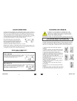
AUDIO CONNECTIONS
Never attach the speakers to a wall that might contain electrical wiring or plumbing.
IF YOU ARE UNSURE ABOUT ANY OF THESE INSTRUCTIONS,
PLEASE CONTACT A PROFESSIONAL CUSTOM AUDIO INSTALLER.
The below mounting procedure applies to drywalls, drywall ceiling and drop ceiling
or similar. You will have to cut a hall in a wall or ceiling, with the right tools and a
little extra care and preparation installing this speaker can be both quick and easy.
MOUNTING THE SPEAKERS
Installation of your KT ceiling speakers is designed to be simple
and intuitive, it is largely advised to consult a professional installer.
Make sure the materials on which you plan to mount the speakers
can support the weight of the speakers.
The speaker terminal can accommodate up to 10 AWG speaker cables (some models can accommo-
date 14 AWG. 10 or 14 AWG speaker cables are connection greater than 20 meters \ 66 ft. For shorter
length you can use 16 or 18 AWG speaker cable. it is recommended to leave about 150 cm (5 ft.) of
extra cable at the speaker end and to facilitate positioning and installation of the speaker. please be
advised not to use stables, nails or any other metallic objects to secure speaker cables. by separating
the speaker audio line from other cables such as electronic or communication lines you will
diminish the chances of getting Hums or distortion through the speaker.
When connecting the speaker it is very important the
you do not reverse the polarity of the sound the source.
please connect to the speaker’s input terminal Red (+)
with Red (+) and Black (-) with Black (-). before connecting
the speaker make sure your amplifier is switched off.
please refer to you amplifier’s instruction manual for more information.
WARNING! Before connecting you amplifier please make sure that your amplifier is designed to work
with your specific KT speaker impedance requirements. you may cause a malfunction in your amplifi-
ers and speakers if they do not match. it may also void your warranty.
OTHER AUDIO CONNECTIVITY
AVAILABLE ONLY ON STEREO MODELS
CONNECT A SINGLE SPEAKER TO TWO AMPLIFIER SPEAKER OUTPUT TERMINALS. CONNECT ONE AMPLIFIER SPEAKERS
OUTPUT TERMINAL WITH ONE SPEAKER INPUT TERMINAL (RED (+) BLACK (-))
CONNECT THE OTHER AMPLIFIER SPEAKERS OUTPUT TERMINAL WITH THE
OTHER SPEAKER INPUT TERMINAL (RED (+) BLACK (-))
STEREO CONNECTION
CONNECT A SINGLE SPEAKER TO A SINGLE AMPLIFIER SPEAKER OUTPUT TERMINALS. CONNECT ONE AMPLIFIER SPEAK-
ERS OUTPUT TERMINAL WITH ONE SPEAKER INPUT TERMINAL (RED (+) BLACK (-))
USING A SHORT PIECE OF SPEAKER CABLE CONNECT ONE SIDE OF THE SPEAKER
INPUT TERMINAL TO THE OTHER SPEAKER INPUT TERMINAL. MAKE SURE YOU
CONNECT RED WITH RED AND BLACK WITH BLACK
MONO CONNECTION
1. Carefully cut a hole drawn on the paper template
(included).
2. Position the template (now a border) where you have
chosen to mount the speaker and draw a line on the wall
or ceiling along the inside edge of the template.
3. Make your cuts along the line in the wall or ceiling. try
to keep the cuts neat, however, the frame of the speaker
will overlap the hole to hide any rough edges.
4. Run the speaker cables while leaving a 150cm (5 ft.) of
extra cable at the hole.
5. Remove the speaker grill by pressing the mounting
screws from the back of the speaker.
6. Connect the speaker cables to the speaker’s terminal
according to your setup..
7. With the grill removed, insert the speaker into the
mounting hole.
8. Use a screwdriver to turn the mounting screws slowly
clockwise.
9. The cut edges of the wall or ceiling will be caught firmly
in between the mounting clamps and the speaker frame.


