


5.5.
(1)
Insta
(Termina
(2)
Unta
(3)
Afte
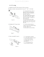
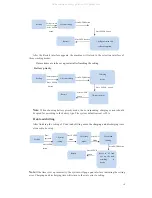
.2 PV wiri
allation instruc
als are polarized
angling the PV
er removing the
Figure 17
Figure 16
ing
tions for the co
d
,
please pay a
wiring termina
e PV connector
Figure 18
onnection of PV
attention to the
al
①
sh
ou
an
②
th
m
st
③
1
th
lo
①
t
②
s
V wiring termin
sign of “+” and
①
Recommen
hould be PV ca
uter diameter b
nd Ø6mm respe
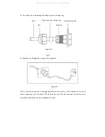
②
Insert the st
he spring with y
make sure the sp
tep 2 in Figure1
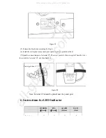
③
Butt connec
6).Tighten up t
he fastening rin
ock it up.
①
Insert the s
test pen into the
②
While withd
screwdriver,pul
①
Loosen fa
②
Pry the lo
is shown in St
③
Pull out o
connecting wi
④
Pry the sp
screwdriver an
al
d “-” on the bod
ded PV input c
able with the inn
being 12AWG (
ectively.
tripped cable, a
your thumb or p
pring is closed (
16).
ctors (refer to F
the cable fasten
ng to the O-ring
slotted screwdriv
e position shown
drawing the
l the connector
fasteners of the c
ocking crank de
tep2 in the pictu
of the ferrule of
ire
pring open with
nd exit the cable
dy)
cable: it
nerand
(4mm²)
and press
pliers to
(refer to
Figure
ners. Screw
g, and then
ver or
n in the figur
outward
cable
evice open as
ure
f the
h a
e
All manuals and user guides at all-guides.com


