KSI ECOTROC ATCN 15-110 Operating Manual Download Page 16

16

Operating Manual ECOTROC ATCN 15-110

Should you have to disconnect the oil vapour adsorber from the mains, e.g. for a maintenance 
operation, make sure that this work is only carried out when the device is free from pressure. 

Wear your personal protective equipment. Proceed as follows:

1.  Close the cut-off valves at the inlet and outlet of the adsorber. 

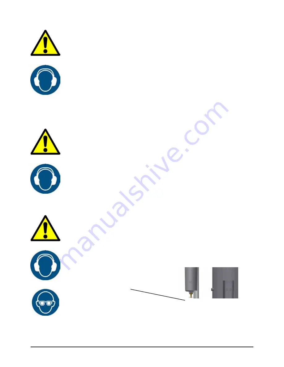
2.  Open the manual drain on the after-filter housing. 

3.  Keep an eye on the pressure gauge and wait until it displays „0“ bar before starting 

work.

4.  Then close the manual cock again.

The oil vapour adsorber is now disconnected from the mains.

8.2 Pressurisation

Only once you‘ve successfully completed all of the checks listed in Section 8.1 can you perform 
the following steps in the specified order. 

Wear ear protection for this as the flow noise can get very loud.

1.  Make sure that the compressed air system is under pressure upstream of the adsorber.
2.  Slowly open the cut-off valve upstream of the adsorber until you hear the flow noise.
3.  Keep an eye on the pressure gauge on the vessel. Pressurisation must rise slowly.
4.  At 4 bar close the inlet shut-off device again. Check all connections for leaks. If leaks are 

found, the adsorber must be rendered pressureless again and the leaks must be re-
paired.

5.  If no further flow noises can be heard and if the pressure gauge does not indicate any 

further increase in pressure, you can open the cut-off valve completely.

Pressurisation has been successful. Check whether the compressed air system downstream of 
the adsorber can be opened safely. Then proceed as follows:

1.  Slowly open the cut-off valves at the outlet of the adsorber until you hear the flow noise.
2.  Keep an eye on the pressure gauge. Should the pressure suddenly drop, check whether 

any tapping points are still open. 

3.  If the pressure remains stable and you no longer hear any flow noise, the cut-off valve 

downstream of the adsorber can be opened completely.

4.  The oil vapour adsorber is now ready for operation.

8.3  Mains operation

Manual drain cock

8.4  Disconnecting from the mains

Summary of Contents for ECOTROC ATCN 15-110

Page 1: ...Operating Manual ECOTROC ATCN 15 110 ECOTROC ATCN 15 110 Operating Manual Oil Vapour Adsorber Rev 01_0918...

Page 2: ...erating manual 5 1 6 Signs and symbols used 6 2 Intended purpose use 7 2 1 Intended use 7 2 2 Performance data 8 3 Safety notes 9 3 1 Signs and symbols 9 3 2 Danger zones 10 4 Technical product data 1...

Page 3: ...8 1 Commissioning prerequirement 15 8 2 Pressurisation 16 8 3 Mains operation 16 8 4 Disconnecting from the mains 16 9 Maintenance 17 9 1 Regular maintenance work 17 9 2 Daily checks 17 9 3 Checking t...

Page 4: ...e que ries It also simplifies the provision of spare parts and support This may correspond to separate pieces of equipment for the individual devices 1 1 System data Model Order No Vessel No Serial nu...

Page 5: ...tion is selected 1 5 Operating manual This operating manual will help clarify any outstanding questions concerning the setup installation operation maintenance repair and disposal of the dryer It cont...

Page 6: ...r Caution Warning This symbol indicates general hazards or dangerous situations Slip hazard This symbol warns of the risk of slipping Wear ear protectors Note This symbol indicates instructions for th...

Page 7: ...is to be used with other gases this must be agreed with the manufacturer Other safety guidelines may apply here The oil vapour adsorber must be set up at a site indoors which is suitable for the weigh...

Page 8: ...s may be detrimental to the service life of the active carbon Moisture and particles are stored in the open pores and reduce the adsorption capacity of the active carbon Where temperatures are above 5...

Page 9: ...dividual chapters Observe all legal guidelines and safety regulations the latter may vary from region to region Observe all local site regulations which are stipulated for the field of application 3 1...

Page 10: ...ipping due to spilt active carbon Always check that the indicator pipe is secure before you open the needle valve and remember to wear eye protection Never operate the device if there is apparent dama...

Page 11: ...ompressed air inlet 2 Compressed air outlet 3 Filling and draining nozzle 4 Pressure gauge 5 Vessel plate 6 After filter 7 Manual drain cock 8 Type plate 1 Compressed air inlet 2 Lifting lugs 3 Pressu...

Page 12: ...ir then exits the vessel again through a sieve on the outlet As the temperatures rise the performance of the active carbon is reduced since the hydrocar bon chains oils become shorter and shorter and...

Page 13: ...ovide suitable assistive equipment Secure the adsorber against tilting using suitable means Do not remove the packaging material until the device is moved to its place of installation Only appropriate...

Page 14: ...nd an air cauldron also has the advantage in that pulsating com pressed air is buffered and the temperature at the inlet of the adsorber is lower Choose a place of installation with the lowest possibl...

Page 15: ...ich are under pressure The pipelines must held in place with brackets the adsorber is not designed to act as a support for the pipes The adsorber must only be used in the predetermined operating condi...

Page 16: ...ut off valve upstream of the adsorber until you hear the flow noise 3 Keep an eye on the pressure gauge on the vessel Pressurisation must rise slowly 4 At 4 bar close the inlet shut off device again C...

Page 17: ...ly be carried out by suitably qualified personnel Make sure that the device is free from pressure before starting work and observe the applicable accident preven tion regulations for the place of inst...

Page 18: ...s with the corresponding measurement pressure to determine the ppm con tent for the corresponding measurement time 7 If your measurement value is within the table values e g 0 5 scale units are discol...

Page 19: ...4 0 6 0 8 1 0 1 2 1 4 1 6 Wert auf der Skala Table for measurement pressure greater than 7 bar g residual oil content in ppm Table for measurement pressure 6 bar g residual oil content in ppm 4 4 5 5...

Page 20: ...6 0 760 0 632 0 508 0 380 0 252 0 192 0 124 0 114 0 101 0 088 0 076 0 064 0 051 0 037 0 027 0 012 0 006 2 100 2 100 1 908 1 704 1 500 1 314 1 140 0 948 0 762 0 570 0 378 0 288 0 186 0 172 0 151 0 132...

Page 21: ...required rec after 4 000 Bh or 1 year Every year Every year when required rec after 4 000 Bh or 1 year Every year Every year when required rec after 4 000 Bh or 1 year Every year Every year when requ...

Page 22: ...the activated carbon material to the lower edge of the upper diffuser At higher filling may lead to increased dust content in the afterfilter 9 Screw the top sealing plug back in again We recommend th...

Page 23: ...ugh the compressor pipes consumer downstream of the adsorber were already contaminated with oil by pass line is open not sealed highly pulsating compressed air filter elements saturated cut off valves...

Page 24: ...O 14121 1 have been adhered to The pressure vessels which are part of these assemblies have been manufactured in construction and design conforming to the European Guideline 2014 68 EU Appendix I for...

Page 25: ...are manufactured in conformity with DIN EN ISO 9001 Technical modi cations and errors excepted KSI Filtertechnik GmbH Siemensring 54 56 D 47877 Willich Tel 49 2154 89108 0 Fax 49 2154 89108 282 www ks...

Reviews: