


RWCP, RWCN
12
Type of grease:
We recommend using lytic-based lubrication grease with
antioxidant additives, of consistency 3 in line with DIN-51502
K3K.
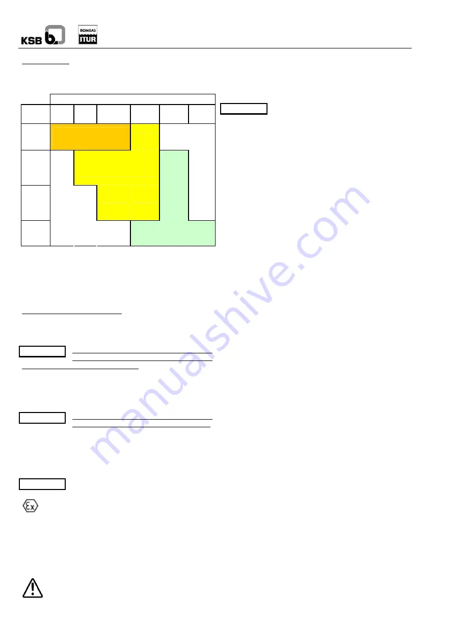
MOTOR
FRAME
PUMP
80 to
90 S/L
100L
to
112M
132 S/M to
180 M/L
200L to
225 S/M
250M to
280 S/M
315S/M
50/160
50/200
65/200
Bearing: 2 x 7307
Re-lubrication: 17g
Re-filling: approx. 25g
65/315
80/250
100/250
100/315
Bearing: 2 x 7310
Re-lubrication: 30 g
Re-filling: approx. 70g
80/400
100/400
150/315
200/315
125/500
150/500
200/400
Bearing: 2 x 7314 + 6314
Re-lubrication: 80 g
Re-filling: approx.180g
FRICTION BEARINGS:
The friction bearings are found in the cover of pumps (always)
and also in the case of double/triple intermediate pipe pumps,
in the intermediate couplings in the intermediate couplings
These bearings must always be lubricated and cooled. There
are three types of lubrication:
1. Lubricated with pumping fluid: If the pumped fluid is clean
(without particles in suspension) and non-aggressive, the
friction bearings are lubricated with the pumped fluid.
Lubricant is not required.
2. Lubricated with external fluid PUMPS
WITH EXTERIOR AUXILIARY
CONNECTION IN THE BASE PLATE: For this purpose there
is an adapter in the base plate which the customer will inject
with clean water or another fluid compatible with the pumped
fluid at a pressure of approximately 3 kg/cm
2
(manometer).
The flow necessary per bearing can be seen in the chart in
annex
3. Lubricated WITH AUTOMATIC
LUBRICATION PUMP IN THE BASE PLATE:
The auxiliary pump has a container with grease to lubricate
the bearings. We recommend using lytic-based lubrication
grease with antioxidant additives, of consistency 2, in line with
DIN-51502 class K2K. The auxiliary pump does not require
maintenance, although the container must contain grease at
all times.
The automatic pump container must be filled
with grease before starting up.
Excessive wear of the bearings may cause friction of
the metal parts, thus locally increasing the
temperature. The pump shall have forced refrigeration from
the pumping fluid if it is clean, or with exterior lubrication of
clean liquid if the pumping fluid is dirty. In the latter case, the
plant operator must maintain a permanent input of clean liquid
to ensure the correct maintenance of the bearing refrigeration
fluid and conducts.
7.3 Emptying/Drainage
The emptying and drainage of pumps used to expel
liquids which are a health hazard must be carried out
in such a way as there is no risk to people or to the
environment, in line with legislation. If necessary, use
protective clothing and mask.
7.4 Dismantling
7.4.1 Fundamental
instructions/observations
Before dismantling, ensure the pump cannot
be started up.
Note
The suction and impulsion valves must be closed.
The pump frame must have returned to environmental
temperature.
The pump frame must be emptied.
Comply with all safety measures in accordance with
When working on the motor, also take into account the rules
and instructions of the manufacturer.
7.4.2 Coupling
Motor pump coupling
- Release
the
motor attachment screws and remove the
motor along with the male coupling.
-
The rubber plugs can then be extracted from the female
coupling.
-
If you need to release the coupling, use an extractor.
Never bang in order to extract, as this may cause serious
damage to the bearings.
Intermediate coupling
-
Release the cover halves on both ends of the coupling.
-
Uncouple the two shafts by gently and uniformly banging
the coupling with a plastic hammer.
7.4.3 Mechanical
seal (when fitted)
In order to have access to the mechanical seal, it is necessary
to dismount almost the whole pump as described in point
(until the seal dismantling section is reached). Once this
process is complete:
Note
-
Release the joining screws between fixing ring and cover
and slide the fixing ring carefully together with the
drainage sleeve along the shaft towards pump side until
the ring is taken out.
- Release the keep pins from the rechangable bushing
and slide this together with the mobile part of the
mechanical seal along the shaft towards pump side until
bushing is removed.
Note
- Slide (towards pump side) and remove carefully the
assembly composed by mechanical seal cover and the
static part of the mechanical seal. Once this assembly is
removed proceed to dismantling of the mechanical seal.
Note
- Release the joining Allen screws between cover and
mechanical seal cover.
-
Release the static part of the seal pushing from top side
of the mechanical seal cover taking care for not to touch
the rubbing face of the seal.
7.4.4
Packing (where fitted)
In order to access the seal, first dismount almost all the pump
as described in point - (until the packing dismantling section is
reached). Once this process is complete:
-
Release the packing gland.
-
Slide and extract the cover with the packing along the
shaft towards the pump side.


