KSB EMV Series Installation & Operating Manual Download Page 5

1 General

5 of 54

EMV

7138.82/01-EN

1 General

1.1 Principles

This operating manual is valid for the type series and variants indicated on the front
cover.

The operating manual describes the proper and safe use of this equipment in all
phases of operation.

The name plate indicates the type series and size as well as the main operating data
and the serial number. The serial number uniquely describes the product and is used
as identification in all further business processes.

In the event of damage, immediately contact your nearest KSB service facility to
maintain the right to claim under warranty.

1.2 Target group

This operating manual is aimed at the target group of trained and qualified specialist
technical personnel.
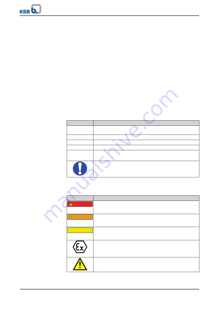
1.3 Symbols

Table 1: 

Symbols used in this manual

Symbol

Description

Conditions which need to be fulfilled before proceeding with the
step-by-step instructions

Safety instructions

Result of an action

Cross-references

1.

2.

Step-by-step instructions

Note
Recommendations and important information on how to handle
the product

1.4 Key to safety symbols/markings

Table 2: 

Definition of safety symbols/markings 

Symbol

Description

!

DANGER

DANGER


This signal word indicates a high-risk hazard which, if not avoided,
will result in death or serious injury.

!

WARNING

WARNING


This signal word indicates a medium-risk hazard which, if not
avoided, could result in death or serious injury.

CAUTION

CAUTION


This signal word indicates a hazard which, if not avoided, could
result in damage to the machine and its functions.

Explosion protection


This symbol identifies information about avoiding explosions in
potentially explosive atmospheres in accordance with EU Directive
2014/34/EU (ATEX).

General hazard


In conjunction with one of the signal words this symbol indicates a
hazard which will or could result in death or serious injury.

Summary of Contents for EMV Series

Page 1: ...Control Valve Actuators EMV For the BOA Control PIC Type Series Installation Operating Manual ...

Page 2: ...s provided herein must neither be distributed copied reproduced edited or processed for any other purpose nor otherwise transmitted published or made available to a third party without the manufacturer s express written consent Subject to technical modification without prior notice KSB SE Co KGaA Frankenthal 11 10 2021 ...

Page 3: ...esign details 12 4 5 Function 13 4 6 Noise characteristics 13 5 Installation 14 5 1 Safety regulations 14 5 2 Checking prior to installation 14 5 2 1 Dimensions and weights of actuators 15 5 3 Installation position 16 5 4 Manual override 17 5 5 Mounting the EMV211 actuator 19 5 5 1 Mounting the actuator 19 5 5 2 Electrical connection 19 5 6 Mounting the EMV212 144 EMV 212 146 and EMV212 147 actuat...

Page 4: ...g to service 34 7 Servicing Maintenance 35 7 1 Safety regulations 35 7 2 Removing the actuator 35 7 2 1 Removing the EMV211 actuator 35 7 2 2 Removing the EMV212 144 EMV 212 146 and EMV212 147 actuators 36 7 2 3 Removing the EMV212 148 and EMV212 150 actuators 37 7 2 4 Removing the EMV213 145 and EMV213 147 actuators 38 7 2 5 Removing the EMV213 148 and EMV213 150 actuators 38 7 2 6 Removing the E...

Page 5: ... be fulfilled before proceeding with the step by step instructions Safety instructions Result of an action Cross references 1 2 Step by step instructions Note Recommendations and important information on how to handle the product 1 4 Key to safety symbols markings Table 2 Definition of safety symbols markings Symbol Description DANGER DANGER This signal word indicates a high risk hazard which if n...

Page 6: ...on with one of the signal words this symbol indicates a hazard involving electrical voltage and identifies information about protection against electrical voltage Machine damage In conjunction with the signal word CAUTION this symbol indicates a hazard for the machine and its functions ...

Page 7: ...e actuator is intended for use in building services systems and industrial plants If the motor is used in countries outside the European Community adhere to the regulations applicable to the relevant country Also observe any local and industry specific regulations governing installation and safety 2 2 Intended use Only operate actuators which are in perfect technical condition Do not operate parti...

Page 8: ...make sure it is used Eliminate all electrical hazards In this respect refer to the applicable national safety regulations and or regulations issued by the local energy supply companies 2 7 Safety information for maintenance inspection and installation Modifications or alterations of the actuator are only permitted with the manufacturer s prior consent Use only original spare parts or parts compone...

Page 9: ...livery we recommend that the following measures be taken EMV311 EMV312 Table 3 Ambient conditions for storage Ambient condition Value Storage temperature 20 C to 65 C Humidity 5 to 95 rH EMV311 PRO Table 4 Ambient conditions for storage Ambient condition Value Storage temperature 25 C to 60 C Humidity 5 to 95 rH EMV211 Table 5 Ambient conditions for storage Ambient condition Value Storage temperat...

Page 10: ...acent symbol must not be disposed of in household waste at the end of its service life Contact your local waste disposal partner for returns If the used electrical or electronic equipment contains personal data the operator is responsible for deleting it before the equipment is returned Due to some components the product is classified as special waste 1 Dismantle the product 2 Separate and sort th...

Page 11: ...valves For instance the actuator can be controlled by a thermostat so the room temperature can be controlled by opening and closing the heating circuits or air conditioning circuits 3 point part turn actuator EMV213 147 EMV213 150 The electronic part turn actuator enables the automatic opening and closing of control valves Variable actuating times can be set via DIP switches For instance the actua...

Page 12: ...duct name 6 Supply voltage 7 Frequency 8 Nominal power 9 Storage temperature 10 Enclosure 11 Actuating time 12 Nominal stroke 13 Actuating force 14 Serial number 15 Country of production 4 4 Design details Design Electrothermal actuator Electrothermal continuous action actuator Continuous action actuator 3 point actuator 3 point part turn actuator Operating modes Continuous duty S1 Actuating force...

Page 13: ...normally open open design Mechanical position indicator The position indicator of the NO variant is black The position indicator of the NC variant is red Electrothermal continuous action actuators 24 V AC version in normally closed or normally open design Positioning function 4 5 Function Electrothermal actuators Function Electrothermal actuators contain a temperature sensing material that expands...

Page 14: ... of the body are removed from the actuator coupling area prior to starting the actuator WARNING Incorrect connection to the mains Damage to the mains network short circuit Observe the technical specifications of the local energy supply companies Inspect the power cable for visible damage Never connect damaged power cables CAUTION Painting of pipes Impairment of the valve s function and loss of inf...

Page 15: ...0 0 22 EMV211 147 80 49 73 5 60 0 25 EMV212 144 112 62 71 5 60 0 325 EMV212 145 112 62 71 5 60 0 325 EMV212 146 112 62 71 5 60 0 325 EMV212 147 112 62 71 5 60 0 29 EMV212 148 122 70 107 60 0 73 EMV212 150 122 70 107 60 0 73 EMV213 145 138 70 63 100 0 7 EMV213 147 138 70 63 100 0 7 EMV213 148 196 92 84 100 1 2 EMV213 150 196 92 84 100 1 2 EMV311 NC230 52 44 75 60 0 18 EMV311 NC24 52 44 75 60 0 18 E...

Page 16: ...ways observe the valve s operating manual and the permissible installation position 360 360 360 360 EMV 311 XXX EMV312XXX EMV 211 146 147 EMV 212 148 150 EMV 212 144 145 146 147 EMV213 145 147 EMV213 148 150 Fig 3 Installation position by actuator type Install the actuator with sufficient clearance for removal ð Section 5 2 1 Page 15 ...

Page 17: ... safety device downwards ð The manual override has been enabled 2 Use an Allen key 6 mm to rotate the actuator until it has reached the required position 3 Slide the safety device upwards ð The manual override has been disabled EMV212 144 EMV212 146 EMV212 147 A B Fig 5 Actuators EMV212 144 EMV212 146 EMV212 147 Using the manual override of the actuator A Hole B Strain relief device 1 Remove strai...

Page 18: ...45 EMV213 147 Using the manual override of the actuator 1 Slide the safety device downwards ð The manual override has been enabled 2 Rotate the actuator coupling until the actuator has reached the required position 3 Slide the sliding switch upwards ð The manual override has been disabled ...

Page 19: ...tightening or loosening the threaded ring OK A Fig 7 Mounting the EMV211 actuator A Threaded ring 1 Screw the threaded ring A onto the external thread of the valve 2 Tighten the threaded ring A by hand 5 5 2 Electrical connection DANGER Unintentional contact with live parts Danger of death from electric shock De energise the mains connection Take steps to ensure that the mains connection cannot be...

Page 20: ... Insert a flat head screwdriver into the edges of the cover to lever off and remove the actuator cover Fig 9 Plugging the connector into the socket 3 Plug the connector into the socket ð The connector is engaged 1 2 Fig 10 Fitting the strain relief device in the corresponding recess 4 Fit the strain relief device in the corresponding recess ...

Page 21: ...Closing the actuator cover 5 Hold the strain relief device in place with a finger and close the actuator cover 6 For EMV211 147 Fasten the fastening screw at the actuator cover For the wiring refer to the Wiring diagrams section ð Section 9 1 Page 44 ...

Page 22: ...hten or loosen the threaded ring by hand Do not use any tools for tightening or loosening the threaded ring 1 2 A Fig 12 Mounting the EMV 212 144 212 146 212 147 actuators A Threaded ring 1 Fit the threaded ring A onto the external thread of the valve 2 Tighten the threaded ring A by hand 5 6 2 Electrical connection DANGER Unintentional contact with live parts Danger of death from electric shock D...

Page 23: ...the strain relief device B A Hole B Strain relief device 1 Remove the cross recessed head screw with a screwdriver Remove the strain relief device B 2 Guide the power cable into the freely accessible opening 3 Connect the cores in accordance with the wiring diagram ð Section 9 1 Page 44 4 Fit the strain relief device B Fit and tighten the cross recessed head screw with a screwdriver ...

Page 24: ...s for tightening or loosening the threaded ring A C D Fig 14 Mounting the EMV 212 148 and 212 150 actuators A Threaded ring C Adapter D Stem extension 1 Screw adapter C onto the thread of the valve tightening torque approx 8 10 Nm 2 Fit the stem extension D onto the valve stem 3 Mount the actuator on the valve Screw it on with the threaded ring A Fig 15 Using the manual override to close actuators...

Page 25: ...tion Take steps to ensure that the mains connection cannot be re energised unintentionally CAUTION Improper electrical connections Damage to the device Check the electrical connection Observe the wiring diagrams The power cable is included in the scope of supply The power cable is connected to the actuator For the wiring refer to the Wiring diagrams section ð Section 9 1 Page 44 ...

Page 26: ...h an Allen key 3 mm 3 Screw the valve stem to the actuator with an Allen key 4 mm tightening torque approx 7 9 Nm 5 8 2 Electrical connection DANGER Unintentional contact with live parts Danger of death from electric shock De energise the mains connection Take steps to ensure that the mains connection cannot be re energised unintentionally CAUTION Improper electrical connections Damage to the devi...

Page 27: ...fastening piece upwards and remove it 3 Pull the metal sheet with directional arrow upwards and remove it 8 6 7 Fig 18 Mounting the EMV213 148 and EMV213 150 actuators 4 Place the actuator on the fixing plate of the control valve Make sure that the valve stem slides into the opening of the actuator 5 Screw the actuator to the fixing plate 6 Position the metal sheet with the directional arrow in mi...

Page 28: ...tion Take steps to ensure that the mains connection cannot be re energised unintentionally CAUTION Improper electrical connections Damage to the device Check the electrical connection Observe the wiring diagrams The power cable is included in the scope of supply The power cable is connected to the actuator For the wiring refer to the Wiring diagrams section ð Section 9 1 Page 44 ...

Page 29: ...g 1 Screw the threaded ring A onto the external thread of the valve 2 Tighten the threaded ring A by hand 5 10 2 Electrical connection DANGER Unintentional contact with live parts Danger of death from electric shock De energise the mains connection Take steps to ensure that the mains connection cannot be re energised unintentionally CAUTION Improper electrical connections Damage to the device Chec...

Page 30: ...f the corresponding accessories 6 2 Commissioning Start up 6 2 1 Commissioning starting up the EMV211 146 and EMV211 147 actuators The actuators do not require any further settings to be made They can be controlled directly after they have been mounted and connected to the power supply 6 2 2 Commissioning starting up the EMV212 146 and EMV212 147 actuators The actuators do not require any further ...

Page 31: ...ed range 4 Defined stroke 4 Auto stroke 5 4 20 mA 5 Voltage range 6 Stroke setting 6 Automatically calibrated stroke Table 13 Setting the length of stroke via DIP switches 1 and 6 DIP switch ON OFF Length of stroke mm 1 5 6 1 5 5 6 1 2 5 6 1 3 5 6 For the BOA Control PIC valves spring return valves DIP switch 4 is set to ON defined stroke This overrides the function of DIP switch 1 and DIP switch ...

Page 32: ...rgised Fig 23 Actuators EMV212 148 EMV212 150 and EMV213 145 EMV213 147 Removing the cover 1 For EMV212 148 EMV212 150 EMV213 145 EMV213 147 Lever off the rubber cover with a flat head screwdriver and fingers Fig 24 Actuators EMV213 148 EMV213 150 Removing the cover 2 For EMV213 148 and EMV213 150 Undo the fastening screw with a Phillips screwdriver Remove the cover ð DIP switches S1 S3 are access...

Page 33: ...troke Stroke Stroke Stroke Stroke Stroke Signal Signal Signal Signal Signal Signal Signal Signal Signal Signal Fig 26 Setting the characteristic curves behaviour 4 Set the characteristic curves behaviour via DIP switches S2 and S3 6 2 5 Commissioning starting up the EMV311 and EMV312 actuators The actuators do not require any further settings to be made They can be controlled directly after they h...

Page 34: ...to 50 C Ambient temperature EMV311 5 C to 50 C Ambient temperature EMV312 5 C to 50 C Humidity 5 to 95 rH 6 4 Shutdown 6 4 1 Measures to be taken for shutdown 1 Disconnect the equipment from the power supply 2 Secure against unauthorised start up 6 5 Returning to service For returning the equipment to service observe the sections on commissioning start up ð Section 6 2 Page 30 and the operating li...

Page 35: ... time After switching off the frequency inverter wait 10 minutes until dangerous voltages have discharged Ensure that the actuator cannot be switched on unintentionally WARNING Insufficient stability Risk of crushing hands and feet Secure the actuator against tilting or tipping over during installation dismantling NOTE All maintenance work service work and installation work can be carried out by K...

Page 36: ... 212 146 and EMV212 147 actuators ü The actuator has been de energised CAUTION Incorrect installation removal of the actuator with tools Damage to the actuator Only tighten or loosen the threaded ring by hand Do not use any tools for tightening or loosening the threaded ring 1 2 A Fig 28 Removing the EMV212 144 EMV212 146 EMV212 147 actuators 1 Unscrew the threaded ring A from the external thread ...

Page 37: ...val of the actuator with tools Damage to the actuator Only tighten or loosen the threaded ring by hand Do not use any tools for tightening or loosening the threaded ring 1 2 3 A Fig 29 Removing the EMV212 148 and EMV212 150 actuators 1 Press the safety catch upwards and hold it in this position 2 Unscrew the threaded ring A counter clockwise 3 Remove the actuator from the valve ...

Page 38: ...t between the actuator and the fixing plate of the control valve 3 Remove the actuator from the fixing plate of the valve 7 2 5 Removing the EMV213 148 and EMV213 150 actuators ü The actuator has been de energised 1 2 3 Fig 31 Removing the EMV213 148 and EMV213 150 actuators 1 Remove the circlip 2 Undo and remove the fastening piece with an open ended spanner 3 Remove the metal sheet with directio...

Page 39: ...he threaded ring A Fig 32 Removing the EMV311 and EMV312 actuators 1 Unscrew the threaded ring A from the external thread of the valve by hand 2 Remove the actuator from the valve 7 3 Maintenance inspection The actuators are maintenance free 7 4 Lubrication The gear unit is lubricated for life and does not need to be re lubricated 7 5 Cleaning CAUTION Improper cleaning of actuators Damage to the a...

Page 40: ... Section 5 10 1 Page 29 Connect the power cable and the control cable Mechanically secure them in front of the terminals to prevent loosening EMV211 ð Section 5 5 2 Page 19 EMV212 144 EMV 212 146 and EMV212 147 ð Section 5 6 2 Page 22 EMV212 148 and EMV212 150 ð Section 5 7 2 Page 25 EMV213 145 and EMV213 147 ð Section 5 8 2 Page 26 EMV213 148 and EMV213 150 ð Section 5 9 2 Page 28 EMV311 EMV312 ð...

Page 41: ...ously B Green LED flashing C Green LED OFF D Red LED lit continuously E Red LED flashing F Red LED OFF Table 15 Trouble shooting for statuses A B C D E F Status Possible cause Remedy Actuator moving into limit position Actuator in limit position Actuator in calibration phase No input signal Signal cable damaged Check electrical connection and power cable for any damage Signal cable not connected E...

Page 42: ...es A B C Status Possible cause Remedy Actuator moving into limit position Actuator in limit position Actuator in calibration phase Actuator not responding Signal cable damaged Check electrical connection and power cable for any damage Signal cable not connected Electronic components defective Actuator has to be replaced Actuator not moving Actuator stem broken Actuator has to be replaced ...

Page 43: ... Green and red LEDs flashing simultaneously fast Table 17 Trouble shooting for statuses A B C D E F G H I J K L Status Possible cause Remedy Actuator stopped Actuator stopped unexpectedly Signal cable damaged Check electrical connection and power cable for any damage Signal cable not connected Low supply voltage Power cable overloaded Check supply capacity Actuator OFF or reset low supply voltage ...

Page 44: ...agram EMV211 146 and EMV211 147 3 point BK Blue OR Orange RD Red EMV212 144 EMV212 145 EMV212 146 EMV212 147 EMV 212 146 24 V AC EMV 212 147 230 V AC RD WH BU GN YE GN BN 24 V AC Open Stop Closed Input signal Output signal a b Fig 34 Wiring diagrams a EMV212 146 and EMV212 147 3 point b EMV212 144 and EMV212 145 continuous action GN Green BN Brown RD Red BU Blue WH White YE Yellow ...

Page 45: ... DC EMV 212 148 24 V AC DC EMV 212 150 230 V AC Fig 35 Wiring diagrams a EMV212 148 continuous action b EMV212 148 and EMV212 150 3 point BK Blue BN Brown RD Red BU Blue GY Grey EMV213 147 EMV213 150 230 V AC Open Stop Closed Fig 36 Wiring diagram EMV213 147 and EMV213 150 BK Blue BN Brown BU Blue ...

Page 46: ... EMV213 145 and EMV213 148 continuous action b EMV213 145 and EMV213 148 3 point BK Blue BN Brown RD Red BU Blue GY Grey EMV311 NC24 EMV311 NO24 EMV311 NC230 EMV311 NO230 EMV312 NO24 EMV312 NO230 N L Electrothermal Thermostat Fig 38 Wiring diagram EMV311 NC24 EMV311 NO24 EMV311 NC230 EMV311 NO230 EMV312 NO24 EMV312 NO230 N Blue L Brown ...

Page 47: ...9 Related Documents 47 of 54 EMV 7138 82 01 EN EMV311 PRO WH BN BU 24 V AC Input signal Fig 39 Wiring diagram EMV311 Pro BN Brown BU Blue WH White ...

Page 48: ...wing directives regulations as amended from time to time 2011 65 EU Restriction of the Use of Certain Hazardous Substances in Electrical and Electronic Equipment RoHS 2014 35 EU Electrical Equipment Designed for Use within Specific Voltage Limits Low Voltage The EU Declaration of Conformity was issued in on Frankenthal 12 July 2021 Dieter Hanewald Product Management and Product Development II Fran...

Page 49: ...8 EMV213 147 EMV213 145 is in conformity with the provisions of the following directives regulations as amended from time to time 2014 30 EU Electromagnetic Compatibility EMC 2014 35 EU Electrical Equipment Designed for Use within Specific Voltage Limits Low Voltage The EU Declaration of Conformity was issued in on Frankenthal 12 July 2021 Dieter Hanewald Product Management and Product Development...

Page 50: ...lowing directives regulations as amended from time to time 2011 65 EU Restriction of the Use of Certain Hazardous Substances in Electrical and Electronic Equipment RoHS 2014 30 EU Electromagnetic Compatibility EMC 2014 35 EU Electrical Equipment Designed for Use within Specific Voltage Limits Low Voltage The EU Declaration of Conformity was issued in on Frankenthal 12 July 2021 Dieter Hanewald Pro...

Page 51: ...damage 5 F Faults Causes and remedies 41 42 43 K Key to safety symbols markings 5 M Maintenance 35 O Operating limits 34 Operating modes 12 P Personnel 7 Preservation 9 Q Qualification 7 R Returning to service 34 S Safety 7 Safety awareness 8 Specialist personnel 7 Storage 9 T Training 7 W Warnings 5 Warranty claims 5 ...

Page 52: ......

Page 53: ......

Page 54: ...KSB SE Co KGaA Johann Klein Straße 9 67227 Frankenthal Germany Tel 49 6233 86 0 www ksb com 7138 82 01 EN ...

Reviews: