5 Installation/Dismantling
17 of 32
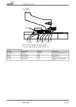
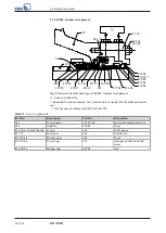
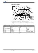
4K / 4KD
G
d
A
K
s
L
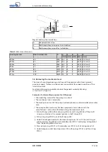
Fig. 3:
Checking the installation
A
Required dimension
L
Reference dimension prior to installation
K
Reference dimension after installation
Table 5:
Reference dimension
Bearing bracket
Nominal diameter
G
d
S
A
L
K
[mm] [mm] [mm] [mm] [mm]
P03ax
40
M6
8,5
2
5
36,00 3,5 to 6,5
P04ax
50
M6
8,5
2
5
35,75 3,5 to 6,5
P05ax
60
M6
8,5
2
5
44,75 3,5 to 6,5
P06x
70
M6
8,5
2
5
50,75 3,5 to 6,5
P08sx
80
M10
13
3
7
52,50 5,0 to 9,0
P10ax
100
M10
13
3
7
52,50 5,0 to 9,0
P12sx
120
M10
13
3
7
54,50 5,0 to 9,0
5.4 Removing the mechanical seal
The rules of sound engineering practice and the pump manufacturer's general
provisions apply. Tidiness and cleanliness are essential for proper execution of the
installation work.
For dismantling and reassembly observe the general assembly drawing.
Example of a dismantling sequence for KSB pumps
ü
The operating manual for the pump is on hand.
ü
The mechanical seal is accessible.
ü
The back pull-out unit of the pump has been placed in a clean and level assembly
area.
ü
The pump and/or machinery has been prepared in accordance with the
manufacturer's instructions for dismantling the mechanical seal.
1.
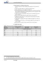
Pull shaft sleeve 523 with mating ring 475.52 and O-ring 412.52 off the shaft
using an extractor in the removal groove in shaft sleeve 523.
2.
Pull mating ring 475.52 out of shaft sleeve 523.
3.
Undo the hexagon head bolts. Remove casing cover 161 with the joint ring as
well as primary ring 472.51 with secondary seal 412.51 and spring arrangement
from the bearing bracket lantern.
4.
Press primary ring 472.51 with secondary seal 412.51 out of casing cover 161.
5.
Undo hexagon socket head cap screws 914 with springs 477.51 and thrust ring
474.51.
Summary of Contents for 4K Series
Page 1: ...KSB Mechanical Seal 4K 4KD For the KWP Type Series Installation Operating Manual ...
Page 30: ......
Page 31: ......


