KSB ITUR AU Series Instruction Manual Download Page 6


AU


5 Installation 

The design of the pipe systems, anchorings 
and other installation areas corresponds to 

other parties.  KSB ITUR only offers details and comments as 
a help, but does not assume any responsibility with regards to 
the design, assembly and operation of any installation. We 
recommend that customers should check with a specialist in 
the design of castings, pipes, wells, etc, to supplement and 
interpret the information provided by KSB ITUR and to ensure 
proper operation.  

5.1 

Check before assembly 

Before positioning, check that the assembly base is in line with 
the dimensional plan of the equipment. 

The slab upon which the equipment is to be positioned must 
have completely set. 

The concrete used must be of sufficient resistance (minimum 
X0) to allow functional assembly in line with DIN-1045. 

The upper surface of the base must be horizontal and flat. 

If the anchor pins are to be placed in existing holes, place the 
anchor pins in their orifices suspended from the pump. 

Do not connect the suction and impulsion nozzles until the 
equipment is completely installed on its base and the cement 
has completely set. 

5.2 Group 

positioning 

5.2.1 

Groups with horizontal base frame 
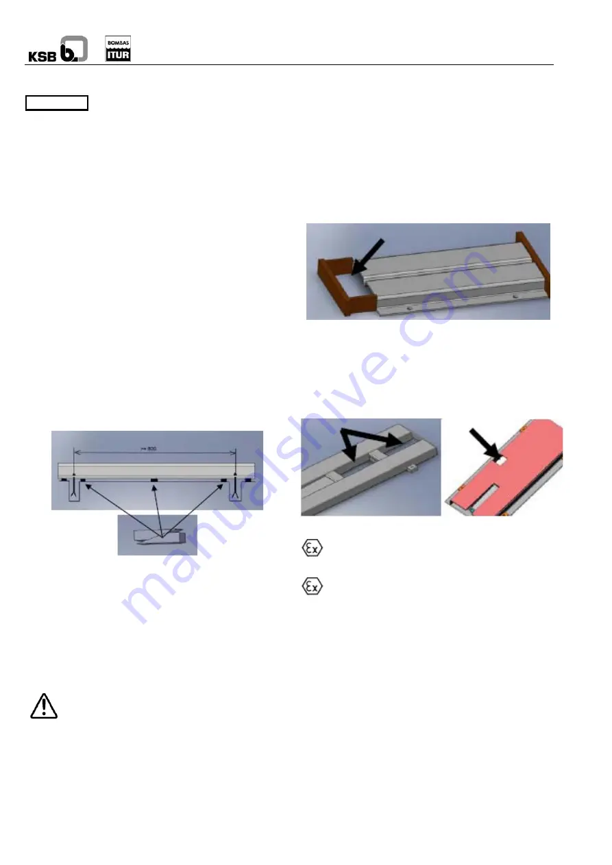
Levelling 


Place wedges on both sides of the anchor pins if the base 
frame does not include levelling screws. 

When the distance between anchor pins is over 800 mm, use 
levelling wedges in the middle, both on the sides and at the 
front. 

Use a spirit level to level the equipment. Use wedges to alter 
the height at different points. The maximum deviation 
permitted is 0.2 mm/m. 

The separation between the two coupling halves must be 
maintained. 

All equipment supplied on a transport bench (forklift 
truck, carriage, etc) should be secured using the 
envisaged attachment device or brake. Ask KSB 

ITUR for the specific instructions manual for your transport 
bench if you do not have one already. (See annex 9.20) 

Cementing 

Pour an initial layer of mortar cement into the orifices of the 
bolts, contacting throughout the periphery with the base of the 
base frame.  Once the mortar cement has set, tighten the 
anchor pins in a balanced manner. 

Note 

Connect the suction and impulsion nozzles to the installation 
and proceed with an initial alignment of the equipment. 

Proceed to fill the lower part, or the cavities between the base 
frame profiles, with concrete. 

When using folded steel base frames, make a small mould in 
the front and rear part. 


The concrete must be of minimum contraction, normal 
granulometry, with a water/cement ratio (W/C Ratio) of

 0.5. It 

is necessary to use additives which improve fluidity for correct 
filling. 

We recommend treating the concrete in line with DIN-1045. 

In order to carry out the final alignment, wait until the 
installation is ready and at operation temperature. 


Pump-motor alignment 

In order to prevent misalignment between the axes, it 
is necessary to correctly install, check and maintain 

the coupling.  See the instructions manual for the coupling. 

The coupling may produce a source of ignition or high 
temperature in the event of incorrect operation. The 

coupling must be classified as non-electric equipment with at 
least the same type of area and temperature as the pump. It is 
necessary to follow the instructions in the coupling manual 
which is included with the pump. 

When the supply includes the complete group (pump – motor), 
the equipment has been aligned at factory, although, due to 
transport and to the anchoring to the casting, the equipment 
should be realigned before proceeding with start-up. 

The correct alignment of the standard KSB ITUR coupling 
involves correcting any possible errors of parallelism and 
concentricity using metal wedges in the motor. 

Use appropriate instruments to carry out the following 
measurements in 4 positions offset 90º between the faces of 
the coupling: 


Summary of Contents for AU Series

Page 1: ...ins important instructions and warnings You must read them before mounting making the electrical connections and starting up You must also comply with the instructions for the components related to this pump Please remember that this Manual must be kept close to the motor pump group ...

Page 2: ...justment 8 5 4 3 Rotation direction Check 8 6 START UP 8 6 1 FIRST START UP 9 6 1 1 Lubricant 9 6 1 2 Filling priming of the pump 9 6 1 3 Final control 9 6 1 4 Start up 9 6 1 5 Shutdown 10 6 2 SERVICE LIMITS 10 6 2 1 Switching frequency 10 6 2 2 Temperature of the liquid to be pumped Error Marcador no definido 6 2 3 Density of the liquid to be pumped 10 6 2 4 Viscosity of the liquid to be pumped 1...

Page 3: ...hazard if not complied with are indicated with a general hazard sign Safety instructions which may involve a hazard to people and facilities if not complied with in accordance with ISO 7000 0434 Safety instructions to prevent electrical hazards in accordance with IEC 417 5036 Safety instructions which may affect the equipment and its operation if not complied with Note The details shown directly o...

Page 4: ...o Directive 94 9 EC Individual pieces supplied as spare parts must be originals supplied and checked by KSB ITUR 3 Transport and storage 3 1 Transport and handling The transport and handling of the equipment must be carried out using suitable means in line with the weight to be supported The weight is generally shown on the delivery note or on the factory plate if it is not and the equipment canno...

Page 5: ...oustic pressure level of these pumps is less than 92 dB A at 1 m in any operation point within the operation range without cavitation The acoustic power is less than 105 dB A 4 5 Forces and moments permitted in the nozzles CAST IRON OR BRONZE CASING 1 SUCTION IMPULSION FORCES N MOMENTS N m FORCES N MOMENTS N m SIZE PUMP Fx Fy Fz Mx My Mz Fx Fy Fz Mx My Mz AU 1 5 AU 2 AU 3 THREADED CONNECTIONS DO N...

Page 6: ...nstructions manual for your transport bench if you do not have one already See annex 9 20 Cementing Pour an initial layer of mortar cement into the orifices of the bolts contacting throughout the periphery with the base of the base frame Once the mortar cement has set tighten the anchor pins in a balanced manner Note Connect the suction and impulsion nozzles to the installation and proceed with an...

Page 7: ...pe from 2 to 3 m s Speed in the suction pipe from 1 to 2 m s Exceeding the admitted stresses of the pipes may lead to leaks in the pump and to the fluid escaping Hazard of death with hot liquids The suction and impulsion nozzle covers of the pump must be removed before connecting the pipes Before starting up a new installation it is necessary to thoroughly clean the tanks pipes and accessories by ...

Page 8: ...a start up the line voltage must coincide with the voltage shown on the motor for delta start up D The six terminals indicated in the following diagram will be connected Connection to the star delta contactor 5 4 2 Time relay adjustment In the star delta start up of three phase motors it is necessary to ensure that the passage from star to delta takes place quickly Prolonged time will cause damage...

Page 9: ...venting plug located in the casing or open a discharge pipe vent before the check valve 4 Partially open the suction valve until the liquid overflows through the vent 5 Close the vent 6 Fully open the suction valve 7 Check the rotation direction of the pump 8 Fully open the discharge valve EQUIPMENT IN SUCTION 1 Disconnect the voltage from the motor or batteries 2 Close the discharge valve 3 Remov...

Page 10: ...mitted operation temperature is indicated in the order and in the ATEX conformity declaration If the pump is to work at a higher temperature or you do not have the data sheet please ask KSB ITUR 6 2 3 Density of the liquid to be pumped The power absorbed by the pump increases in direct proportion to the density of the impelled liquid In order to prevent overloading in the motor pump and coupling t...

Page 11: ...lly The bearing support temperature is less than 40ºC in order to prevent burns to the hands To do this measure the temperature with a thermocouple The absence of oil grease in the bearing support may lead to a lack of lubrication of the lip seals which will come into dry contact with the shaft This contact may lead to a high shaft temperature which might cause ignition To prevent this regularly c...

Page 12: ...mp frame must have returned to environmental temperature The pump frame must be depressurised and emptied Comply with all safety measures in accordance with 7 1 When working on the motor also take into account the rules and instructions of the manufacturer 7 4 2 Tubular coupling guards When dismounting follow the chapters on assembly but in reverse order 7 4 3 Coupling 1 Remove the coupling guard ...

Page 13: ...ly approved quality bearings which are supplied as original spare parts Regularly check the correct state of the protector deflector and replace in the event of deterioration 7 5 Assembly 7 5 1 Tubular coupling guards 1 Install the distancer cylinder and seal using the clamps 1 1 2 Position the side cover 2 leaving the rims 3 in the upper section 3 Join the side cover 2 with the fastening screws 4...

Page 14: ...ow of the cover 161 Check the correct location of pieces especially the seals and impellers and tighten the impeller nuts as shown in the chart in point 7 5 6 Note Do not forget to position all the safety and protection elements such as coupling guards before starting up the equipment The pump materials have been selected in accordance with the process fluid indicated in the datasheets If this flu...

Page 15: ...he bearings With thermocouple Quarterly 2 5 12 7 Check tightness of connecting bolts for motor base frame pump base frame cover casing support support supplement flanges casing Manually Twice a year 17 8 COMPLETE PUMP CHECK Checking and dismounting the pump See point 7 of the manual Yearly 1 3 4 6 7 9 10 12 13 14 9 Check for wear of the impeller and rings Dismount casing visual inspection Yearly 1...

Page 16: ...ghtness x x x Impeller obstructed deteriorated or imbalanced Dismount the impeller and inspect balance or change it x x Wear rings deteriorated or incorrectly assembled Dismount the rings and change them x Counter pressure too high Increase the rotation speed If this is not possible a larger impeller or larger pump needs to be assembled Please ask x Liquid viscosity or density greater than normal ...

Page 17: ... foot 484 Fixing washer 914 Allen screw 210 Shaft 507 Deflector protection 920 Nut 230 Impeller 523 Shaft wearing sleeve 922 Impeller nut 320 Bearing 554 Flat washer 923 Bearing nut 331 Bearing bracket 636 Grease nipple 931 Lockwasger 341 Pedestal 637 Oil filling plug 932 Circlip 350 Bearing housing 643 Oil dipstick 940 Key 360 Bearing cover 800 Motor 400 Gasket 869 Coupling fastener AU M1 10 AU M...

Page 18: ...507 800 903 2 901 2 411 2 412 902 1 554 1 920 2 902 2 920 3 554 2 523 901 1 019 AU M50 20 AU M50 25 Sectional C 1275 940 1 903 3 412 554 2 920 2 554 3 902 4 940 2 869 554 1 920 3 902 5 901 902 1 411 1 019 920 1 135 922 903 2 411 2 900 903 1 162 920 5 101 902 2 230 161 902 3 433 920 4 210 341 914 ...

Page 19: ... 900 412 902 1 554 920 2 320 1 210 320 2 932 940 2 135 019 901 1 230 922 AU 50 20 AU 50 25 Sectional C 1269 903 1 162 920 1 101 902 2 903 5 230 161 902 3 433 420 637 643 331 360 2 940 1 903 3 412 554 920 3 507 901 2 400 360 1 320 1 903 4 210 320 2 940 2 901 1 902 1 411 1 019 920 2 135 922 903 2 411 2 900 ...

Page 20: ...84 920 3 400 2 902 3 554 2 902 4 360 1 523 320 1 210 183 320 2 940 2 901 2 360 2 400 3 901 3 554 1 920 6 019 902 2 901 1 920 2 161 902 5 135 230 922 AU 80 15 AU 80 22 Sectional C 1271 162 903 1 101 902 1 411 1 433 940 1 161 554 2 320 1 636 320 2 923 903 2 411 2 412 902 3 920 2 932 2 331 210 932 1 931 940 2 922 135 902 2 554 1 920 1 019 901 1 230 900 ...

Page 21: ...40 2 922 135 902 1 554 1 920 1 019 901 230 900 AU 150 25 AU 150 35 AU 150 45 Sectional C 1272 183 902 3 230 554 3 920 3 433 507 320 1 210 920 1 554 1 902 1 400 1 101 162 019 901 1 922 940 1 554 2 920 2 902 2 411 903 1 900 135 523 161 360 1 412 903 2 914 1 350 636 400 2 320 2 360 2 940 2 420 914 2 901 2 AU 200 40A AU 200 40B AU 200 55A AU 200 55B AU 200 68A AU 200 68B ...

Page 22: ... 1334 183 902 3 230 554 3 920 3 433 507 320 1 637 920 1 554 1 902 1 400 1 101 162 019 901 1 922 940 1 554 2 920 2 902 2 411 1 903 1 900 135 523 161 411 2 412 903 2 210 350 400 2 643 320 2 360 940 2 420 901 2 554 4 901 3 ...

Page 23: ...n sloping and clean in order to prevent any displacement If operation is by way of an electric motor with a pluggable connection check that the circuit breaker or operation selector is in shutdown position before connecting to the grid The start up instructions in the pump and motor manuals must be followed 9 2 3 Maintenance Apart from the particular instructions on maintenance of the pump and mot...

Page 24: ...NDER CERTIFICATION PUMPS SERIES AU EC DECLARATION OF CONFORMITY KSB ITUR hereby declares under its responsibility that its aforementioned products when supplied with a motor to which this Declaration refers are in line with European Directive 98 37 EC on the approximation laws of the Member States on machinery Applied harmonised standards EN 292 Part 1 EN 292 Part 2 and EN 809 MANUFACTURER S DECLA...

Reviews: