background image

10

EN  Application sheet

KITCHEN HOODS

lighting. The long time operation of the cooker 

hood lamps may lead to early breakdown of the 

lamps and the cooker hood.

The removal and replacement of the lamps and 

filters is not included in the warranty service.

HOOD INSTALLATION  

INSTRUCTION

Only the specialist has the right to install and 

connect the hood to the mains.

You can not start the installation of the hood and 

remove the protective film from the stainless steel 

hood until you are convinced of the technical con-

dition of the hood by connecting it to the electrical 

network and checking all its functions.

To do this, open the package, remove the hood and 

place it on a flat surface in such a way that switch 

of operating modes is turned towards the inspec-

tor. The hood is then connected to the mains and 

being tested.

If it is working properly at all modes, then you 

should start installing the hood. If not, contact the 

organization where you purchased the hood or the 

warranty workshop. Protective film from stainless 

steel hoods should only be removed after the hood 

has been installed.

We remind you that the height of the hood 

above the electric stove should be at least 65 

cm, and above the gas stove less than 75 cm. 

It is recommended to install this hood together 

with one more person.

Before installing the hood, make sure that the wall 

on which the hood is hung is competent enough. 

To hang the hood and the bracket for securing the 

decorative duct, use screws and dowels, which 

suit the type of walls in your kitchen (reinforced 

concrete, plasterboard, etc). If the screws and 

dowels are included in the kit, you should make 

sure that they are suitable for the type of wall on 

which the hood will be hung.

Install the hood in the following sequence: 

1.   It is necessary to make layout marking on the 

wall before drilling the holes for wall plugs. 

To do the marking apply a template which is 

provided together with the cooker hood to the 

wall at a desirable height and level it up (see 

Pic. 10). Mark the points A, B on the wall, these 

points will match the mounting bracket on the 

back side of the cooker hood.   

2.   Drill two holes 8 mm in diameter at the points 

A, B. The depth of the holes should match the 

length of the wall plugs.

3.   Insert wall plugs Ø 8 into the holes.

4.   Drive two screws into A, B holes so that the 

distance between the wall and the head of the 

screw is 5 mm.

5.   If the diameter adapter with the non-return 

valve is not preinstalled, use two screws 3.5 x 

9.5 to install the adapter at the corresponding 

place on the top of the cooker hood (see Fig. 

10.1).

6.   Hang the cooker hood on the screws A, B.

  Use the level to check the horizontal align-

ment. If necessary level up the horizontal line 

by regulating the height of the right and left 

hooks.

7.   Remove the grease filters, and mark another 

point C on the wall from the inside of the cook-

er hood, as it is shown in the Fig. 10, and take 

the cooker hood off the wall. 


Drill a hole at the point C, insert a wall plug and 

hang the cooker hood back at the points A, B.

8.   Fix the cooker hood by driving a 5.5 x 45 screw 

into the hole C.  

9.   If you use the cooker hood in the extraction 

mode, mount the exhaust pipe on top of the 

diameter adapter. Apply a sealer on the joint 

line of the adapter and the pipe before mount-

ing the pipe, and use a fixing ring to fix the pipe 

on the adapter (the ring should be purchased 

Summary of Contents for 00018393

Page 1: ...KÖÖGI ÕHUPUHASTAJAD HOTTES DE CUISINE CAMPANAS DE COCINA DE Gebrauchs und Wartungsanweisung EN Application sheet RU Инструкция по применению LV Lietošanas instrukcija LT Vartojimo instrukcija ES Kasutamisjuhend FR Guide de l utilisateur SP Guía del usuario www krona steel com PATRICIA 600 inox push button PATRICIA 900 inox push button ...

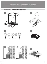
Page 2: ...Application sheet Gebrauchs und Wartungsanweisung KITCHEN HOODS DUNSTABZUGSHAUBEN 7 1 2 4 3 6 5 ...

Page 3: ...Application sheet Gebrauchs und Wartungsanweisung KITCHEN HOODS DUNSTABZUGSHAUBEN 10 1 10 2 10 8 9 ...

Page 4: ...nisses auf Umwelt und Menschen vorbeugen Das Symbol auf dem Erzeugnis bzw auf Begleitpa pieren weist darauf hin dass man es bei der Entsorgung nicht wie einen normalen Haushaltsmüll behandeln darf Statt dessen ist es an eine entsprechende Annah mestelle für elektrische und elektronische Geräte für eine weitere Entsorgung abzugeben Die Müllentsorgung soll nach örtlichen Vorschriften für Müllentsorg...

Page 5: ...Schutzglas der Beleuchtungslampen 5 Außendekorteil des Mantels der Dunstabzugs haube 6 Innendekorteil des Mantels der Dunstabzugs haube Im Gehäuse der Dunstabzugshaube nach Abbau des wiederverwendbaren Alu Fettfilters befinden sich siehe Bild 2 1 Motorgehäuse mit Motor und Flügelrad kom plett 2 Montagekasten 3 Beleuchtungslampen STEUERUNG DER DUNSTABZUGSHAUBE Auf der Vorderseite der Dunstabzugshau...

Page 6: ...Für eine Außenreinigung der Oberflächen aus Stahl Kupfer und Messing sind Extramittel lt ent sprechenden Hinweisen zu verwenden Niemals für Pflege einer Dunstabzugshaube chlor und säure haltige oder Schleifmittel bzw Schwämme verwen den die die Oberfläche angreifen können Der Alu Fettfangfilter verschlämmt sich indem er Fettteilchen und Staub aus der Luft festhält Er ist mit nicht säurehaltigen Mi...

Page 7: ...bzugshaube bei allen Modus einwand frei läuft darf man mit ihrer Installation anfangen ggf muss man sich an den Betrieb wenden wo Sie sie gekauft haben bzw an eine Garantiewerkstatt Es ist ratsam die Schutzfolie von Dunstabzugshau ben aus rostfreiem Stahl nur nach der Beendigung der Installation abzuziehen Wir machen Sie nochmals darauf aufmerksam dass der Mindestabstand über einem Elektro herd 65...

Page 8: ... und weniger Lärm und Vi bration der Dunstabzugshaube ist 11 Wenn die Dunstabzugshaube im Modus Luftumwälzung betrieben wird sind nur De korgehäuse aufzustellen Nr 5 6 Bild 1 Eine Markierung ist vorzunehmen um die Be festigungsleisten des Dekorgehäuses aufzu stellen Bild 10 Punkte E F 12 Zwei Öffnungen mit einem 6 mm Bohrer5 mm unter der Küchendecke bohren 13 In die gebohrten Öffnungen zwei Dübel ...

Page 9: ...od cover 1 4 Adapter flange with non return valve if not installed 1 5 Corrugated air duct 1 6 Decorative cover 2 7 User s manual 1 Package contents are subject to change without notice TECHNICAL FEATURES MODEL PATRICIA push button Overall dimensions mm Width 600 900 Length depth 420 Height min max 447 837 Electric line voltage Frequency 220 240 V 50 Hz Power consumption W Motor 100 Lighting lamps...

Page 10: ...h the motor and fan as sembly 2 Junction box 3 Lamps COOKER HOOD OPERATION There is a push button type control panel for switching the fan speeds and turning on the lights in the centre of the front panel of the cooker hood PATRICIA push button Its elements have the following functions see Fig 3 1 Turning the motor off 2 First fan speed 3 Second fan speed 4 Third fan speed 5 Light on off You can c...

Page 11: ...emperature of 65 C Ex tremely polluted grease trap filters should not be washed in the dish washer along with kitchenware Aluminum filters should be cleaned once in 1 5 2 months which will be reminded by a relevant signal on the display of the kitchen hood remote control see the remote control description in the para graph Kitchen hood control Simultaneously with cleaning of the grease trap fil te...

Page 12: ...and dowels are included in the kit you should make sure that they are suitable for the type of wall on which the hood will be hung Install the hood in the following sequence 1 It is necessary to make layout marking on the wall before drilling the holes for wall plugs To do the marking apply a template which is provided together with the cooker hood to the wall at a desirable height and level it up...

Page 13: ...unting the decorative chimneys connect the cooker hood to the power source 15 Put the internal decorative chimney inside the external chimney Mount the external chimney onto the cooker hood body if there are fixing points on the chimney and the cooker hood body use screws to fix the chimney 16 Lift the internal decorative chimney up to the level where it reaches the fixing bracket and join them to...

Page 14: ...ьные негативные последствия для окружающей среды и здоровья человека Символ на самом изделии или сопроводительной документации указывает что при утилизации данного изделия с ним нельзя обращаться как с обычными бытовыми отходами Вместо этого его следует сдавать в соответствующий пункт приемки электрического и электронного оборудования для последующей утилизации Сдача на слом должна производиться в...

Page 15: ...го алюминиевого жироулавливающего фильтра на ходятся см Рис 2 1 Короб мотора с мотором и крыльчаткой в сбо ре 2 Монтажная коробка 3 Лампы освещения УПРАВЛЕНИЕ ВЫТЯЖКОЙ На лицевой панели вытяжки PATRICIA push button посередине расположен кнопочный пере ключатель режимов работы мотора и ламп осве щения Его элементы имеют следующее функциональ ное назначение см Рис 3 1 Кнопка выключения мотора 2 Вклю...

Page 16: ... хлорсодержащие и кислотосодержащие средства абразивные средства или губки ко торые могут поцарапать поверхность Алюминиевый жироулавливающий фильтр удерживая частицы жира и проходящую через него пыль из воздуха засоряется Его следует чистить не кислотосодержащими средствами или мыть после предварительного отмачивания в горячей воде с помощью эффективного мо ющего средства или если это возможно в ...

Page 17: ...ацию в которой Вы приобрели вытяжку или в гарантийную мастерскую Защитную пленку с вытяжек из нержа веющей стали рекомендуется снимать только по сле окончания монтажа вытяжки Напоминаем что высота установки вытяжки над электри ческой плитой должна быть не менее 65 см а над газовой плитой не менее 75 см Внимание Монтаж этой вытяжки рекомендуется выполнять вдвоем Перед установкой вытяжки проверьте ч...

Page 18: ...вытяжки 11 Если вытяжка будет работать в режиме рецирку ляции то необходимо просто установить декора тивные кожухи 5 6 Рис 1 Сделайте разметку для установки планки кре пления декоративного короба Рис 10 точки E F 12 Просверлить два отверстия сверлом диаметром 6 мм на 5 см ниже потолка кухни 13 В просверленные отверстия установить два дю беля и привернуть планку для крепления декора тивного кожуха ...

Page 19: ...juma utilizāciju jūs palīdzēsiet novērst kaitējuma nodarīšanu apkārtējai videi un cilvēku veselībai Simbols uz paša izstrādājuma vai uz tā pavaddoku mentācijas norāda ka utilizējot šo iekārtu to aizliegts iz mest sadzīves atkritumos Tā ir jānodod atbilstošā speciālā elektrisko un elektronisko iekārtu pieņemšanas punktā sekojošai utilizācijai Nodošana lūžņos jāveic saskaņā ar vietējiem noteiku miem...

Page 20: ...ā daļa 6 Tvaika nosūcēja apvalka iekšējā daļa Tvaika nosūcēja iekšpusē pēc vairākkārt lietojamā alumīnija tauku uztveres filtra noņemšanas atro das sk 2 attēlu 1 Motora kārba ar motoru un samontētiem venti latora spārniem 2 Montāžas kārba 3 Apgaismes lampas TVAIKA NOSŪCĒJA VADĪBA Uz tvaika nosūcēja PATRICIA push button priekšējā paneļa vidusdaļas atrodas tvaika nosūcēja motora darbības režīmu un a...

Page 21: ...ātīra ar skābes nesaturošiem līdzekļiem vai jā mazgā ar efektīvu mazgāšanas līdzekli pēc mērcē šanas karstā ūdenī vai arī ja tas ir iespējams trauku mazgājamā mašīnā 65 C temperatūrā Ļoti netīrus tauku uztveres filtrus nevajadzētu mazgāt trauku mazgājamā mašīnā kopā ar traukiem Alumīnija filtri jātīra apmēram vienu reizi 1 5 2 mēnešos par ko at gādina atbilstošs displeja signāls uz tvaika nosūcē j...

Page 22: ...iģipša siena u c Ja skrūves un dībeļi ietilpst piederumu komplektā jāpārliecinās ka tie ir piemēroti konkrētās sienas pie kuras tiks piekārts tvaika nosūcējs veidam Tvaika nosūcēja montāža jāveic šādā secībā 1 Pirms caurumu urbšanas sienā dībeļu ievieto šanai jāatzīmē vajadzīgie attālumi Lai to izdarī tu jāpieliek kopā ar tvaika nosūcēju piegādātā papīra veidne pie sienas vajadzīgajā augstumā un j...

Page 23: ...eskrūvē dekoratīvā apvalka stiprinājuma plāksne 14 Pirms dekoratīvo apvalku uzstādīšanas tvaika nosūcējs jāpieslēdz elektrotīklam 15 Jāievieto apvalka iekšējā daļa ārējā apvalkā Jā uzstāda apvalka ārējā daļa uz tvaika nosūcēja korpusa ja ir stiprinājuma vietas jāpiestiprina pie korpusa 16 Iekšējo apvalka daļa jāpaceļ augšup līdz apval ka un dekoratīvā apvalka stiprinājuma plāksnes stiprinājumiem u...

Page 24: ...ai utilizuodami šį gaminį Jūs padėsite išvengti po tencialiai negatyvių pasekmių aplinkai ir žmogaus sveika tai Ženklas ant gaminio arba pridedamų dokumentų rodo kad utilizuojant šį įrenginį negalima elgtis kaip su paprastomis buitinėmis atliekomis Vietoj to jis turėtų būti atiduotas utilizuoti į elektros ir elektroninės įrangos per dirbimo įstaigą Atliekų tvarkymas turi būti atliekamas laikantis ...

Page 25: ...ton priekinės pa nelės viduryje yra mygtukinis variklio ir apšvietimo lempų darbo režimo mygtukinis perjungiklis Jo elementai turi šias funkcines reikšmes pieš 3 1 Variklio išjungimo mygtukas 2 Pirmo ventiliavimo greičio įjungimas 3 Antro ventiliavimo greičio įjungimas 4 Trečio ventiliavimo greičio įjungimas 5 Apšvietimo lempų įjungimas išjungimas Šiuo perjungikliu galite įjungti vieną iš trijų va...

Page 26: ...ki te jo aliuminio paviršiaus nes tai yra matoma filtro dalis Nestatykite filtro į gartraukį jam visiškai neiš džiuvus Filtras įstatomas atbuline tvarka Reikia paspausti spyruoklinę spynelę ant filtro ir įstatyti į vietą po to spynelę atleisti Anglies filtrus reikia keisti kartą į penkis mėnesius Jie statomi ant apsauginių variklio grotelių lengvai paspaudus ir pasukant pagal laikrodžio rodyklę žr...

Page 27: ...einamą jungę jeigu jau neįstatyta su atbuliniu vožtuvu atitinkamoje vietoje gartrau kio viršuje Pieš 10 1 6 Ant atramos taškų A ir B pakabinkite gartraukio korpusą Gulsčiuku patikrinkite horizontalumą Jeigu rei kia galite sureguliuoti horizontalumą keisdami kairės ir dešinės ausyčių padėtį 7 Nuėmus aliuminio filtrus iš korpuso vidaus kaip parodyta pieš 10 ant sienos pažymėkite angą C ir nuimkite g...

Page 28: ...INKO Gartraukis jungiamas prie 220 240 V AC 50 Hz įtampos maitinimo tinklo Norint išvengti pažeidimo elektros srove gartrau kis turi būti pajungiamas į įžemintą elektros lizdą Kategoriškai draudžiama montavimo metu nupjauti šakutę Pažeidus elektros laidą jį keisti gali tik kvalifi kuotas specialistas Norint papildomai apsaugoti gartraukį nuo įtam pos šuolių rekomenduojama jį pajungti per papildo m...

Page 29: ... tagajärgi keskkonnale ja inimese tervisele Sümbol esemel või sellega kaasneval dokumentat sioonil viitab sellele et antud eseme utiliseerimisel ei tohi seda käsitleda kui tavalist olmeprügi Selle asemel tuleb see üle anda punkti mis tegeleb elektrilist ja elektroonset inventari utiliseerimisega Käitlemine peab toimuma vastavalt kohalikele seadustele mis reguleerivad jäätmete utiliseerimist Lisain...

Page 30: ...MINE PATRICIA õhupuhastaja esipaneeli keskel asub mootori töörežiimide ja valgustuslampide nuppude lüliti vt joon 3 Selle elementidel on järgmised funktsioonid 1 Mootori väljalülitamise nupp 2 Esimese ventileerimiskiiruse sisselülitamine 3 Teise ventileerimiskiiruse sisselülitamine 4 Kolmanda ventileerimiskiiruse sisselülitamine 5 Valgustuslampide sisse väljalülitamine Selle lüliti abil on Teil võ...

Page 31: ...a juhtimispuldi ekraanil vt puldi kirjeldus Õhupuhastaja juhtimine Samaaegselt rasvafiltri puhastamisega kontrollige ka teisi võimalikke õhupuhastaja korpuse elemen te Alumiiniumist filtri eemaldamiseks joon 7 tuleb vajutada filtril paiknev vedrulukk ning tõmmata see enda peale alla eemaldades see Samal ajal filtri alumiiniumist pealispinnale surudes võivad tekkida mõlgid mis kajastuvad ka filtri ...

Page 32: ...ovitud kõrgu sele ning joondage tasapinnaga vt Joon 10 Märkige seinale punktid A B millele peavad vastama õhupuhastaja tagumise paneeli kin nituskohad 2 Puurige punktides A B kaks ava 8 mm dia meetriga Avade sügavus peab vastama tüüb lite pikkusele 3 Paigaldage 8 mm diameetriga tüüblid puuritud avadesse 3 Keerake kaks puurkruvi kahte ülemisse avasse A B selliselt et vahenaa seina ja kruvipea va he...

Page 33: ...le Kui ühenduskohad lubavad keerate see korpuse külge kinni 16 Tõstke kate sisemine osa üles kate ja deko ratiivümbrise kinnituslati sõlmede liitumiseni ning ühendage need Joon 10 2 ÜHENDAMINE VOOLUVÕRGUGA Õhupuhastaja ühendatakse vooluvõrku pingega 220 240 V 50 HZ Elektrilöögi vältimiseks peab pistik kuhu õhupu hastaja ühendatakse olema maandatud Monteerimisel hargi lühemaks lõikamine on rangelt ...

Page 34: ...omposition de l ensemble fourni comprend 1 Carrosserie d hotte 1 p 2 Kit de montage mural 1 3 Barre de fixation de carter intérieur au mur 1 p 4 Adaptateur de filière avec clapet anti retour si pas installé 1 p 5 Conduit ondulé 1 p 6 Carter décoratif 2 p 7 Guide d installation 1 p la composition peut être changée sans préavis CARACTÉRISTIQUES TECHNIQUES Modèle PATRICIA push button Dimensions mm La...

Page 35: ...intérieur de hotte comprend imm 2 1 Lecarter du moteur moteur à moulinet 2 La boîte d encastrement 3 Les lampes d éclairage CONTRÔLE DE HOTTE La pupitre de modes de fonctionnement du moteur et de lampes d éclairage pour la hotte PATRICIA push button se situe au milieu du panneau avant Ses éléments ont les fonctions suivantes imm 3 1 Arrêt du moteur 2 Mise en marche de la première vitesse de ven ti...

Page 36: ... pas recommandé de nettoyer les filtres trop sales avec la vaisselle dans le lave vaisselle Le filtre doit être nettoyé une fois par 1 5 2 mois lorsque le système d indication de saturation des filtres indique cette nécessité regardez la descrip tion de pupitre dans la partie EXPLOITATION DE HOTTE Nettoyez en même temps tous éléments de la car rosserie de graisse Pour démonter le filtre anti grais...

Page 37: ... conviennent pour votre type de mur Faites le montage dans l ordre suivant 1 Avant de visser les trous il est nécessaire de faire le traçage Attachez le gabarit de mon tage inclus dans le complet au mur à la hau teur nécessaire en fonction de la distance mi nimale entre la table de cuisson et la hotte et alignez le avec une nivelle regardez imm 10 Marquez sur le mur les points A B corres pondants ...

Page 38: ... les points d attache existent fixez le à la carrosserie 16 Montez le carter intérieur pour le joindre avec la barre fixez les par les vis Imm 10 2 BRANCHEMENT ÉLECTRIQUE La hotte se connecte au réseau électrique de la tension 220 240 V 50Hz Il est recommandé de faire le branchement via la prise à contact de protection pour éviter les risques d électrocution Il est interdit de couper la fiche de c...

Page 39: ...tri cos y electrónicos WEEE Al asegurar una eliminación correcta de este producto Usted ayudará a evitar posi bles consecuencias negativas para el medio ambiente y la salud humana El símbolo en el producto o en la documentación de apoyo especifica que no se puede tratar este producto como un residuo doméstico común durante la elimina ción Por el contrario debe ser tomado a la estación co rrespondi...

Page 40: ... reutilizable de grasa de aluminio se en cuentran Fig 2 1 Canal del motor con el motor y el impulsor en la recopilación 2 Caja de montaje 3 Las bombillas de iluminación DESCRIPCIÓN DE LOS MANDOS En el medio de panel frontal de la campana ex tractora PATRICIA push button hay un interruptor digital que controla los modos de funcionamiento del motor y de iluminación de bombillas Sus elementos tienen ...

Page 41: ... por una señal per tinente en la pantalla del control remoto de la campana véase la descripción de la consola en el apartado Descripción de los mandos Simultáneamente con la limpieza del filtro de gra sa limpie de grasa todos los elementos de la car casa de la campana Para desconectar el filtro de aluminio Fig 7 pre sione en la cerradura de resorte del filtro y tirando del mismo hacia usted y haci...

Page 42: ...yeso etc Si los tornillos y ta cos son incluidos en el paquete asegúrese de que sean adecuados para el tipo de pared en la que se suspenderá la campana Instale la campana en la siguiente secuencia 1 Antes de que los orificios de las clavijas de perforación en la pared es necesario hacer las marcas Para ello conecte el adaptador de campana junto con una plantilla de papel para la pared a la altura ...

Page 43: ... carcasa decorativa 14 La campana debe estar conectada a la red an tes de la instalación de las cubiertas decorati vas 15 Colocar el interior de la carcasa exterior Insta lar la parte exterior de la carcasa en el cuerpo de la campana si cualquiera de los puntos de fijación apriételo con la cascara 16 Levante el interior de la carcasa para alinear los puntos de vivienda y de fijación de correa que ...

Page 44: ...ei der Diagnostik durch den Spezialisten des Servicezentrums das Erzeugnis intakt sein wird behält sich das Servicezentrum vor von dem Verbraucher die Ent geltung der unnötigen Anfahrt zu verlangen die nach Tarif bewertet wird Der Hersteller ist für keinerlei Schaden verantwortlich der seinem Verbraucher oder seinem Besitz angerichtet wird führt auch keine kostenlose Reparatur in den folgenden Fäl...

Page 45: ...e trade or ganization and seller s signature including tear off cou pons model and serial number of the product Before calling a service center specialist read the in struction manual of the product carefully If a specialist of the service center correctly diagnoses the product the service center will have the right to demand payment of a false call from the consumer according to the price list Th...

Page 46: ... сервисного центра внимательно прочитайте инструкцию по эксплуата ции изделия Если при диагностике специалистом сервисного центра изделие окажется исправно то за сервисным центром остаётся право требовать от потребителя оплаты ложного вызова согласно прейскуранту Изготовитель не несёт какой либо ответственности за любой возможный ущерб нанесённый потребите лю или его имуществу и не производит бесп...

Page 47: ...noplēšamos ta lonus izstrādājuma modelis un sērijas numurs Pirms izsaucat Servisa centra speciālistu rūpīgi iepa zīstieties ar lietošanas instrukciju Ja servisa centra spe ciālists diagnostikas laikā konstatēs ka izstrādājums funkcionē normāli tad Servisa centrs var izmantot savas tiesības prasīt no apmaksāt nepamatoto izsaukumu pēc cenrāža Ražotājs neuzņemas atbildību par jebkādu iespējamo kaitēj...

Page 48: ...atidžiai perskaitykite gaminio eksploatavimo instrukciją Jei atlikęs diagnostiką techninės priežiūros centro spe cialistas nustato kad gaminys techniškai tvarkingas te chninės priežiūros centras turės teisę reikalauti iš varto tojo apmokėti už klaidinantį iškvietimą pagal kainoraštyje patvirtintus įkainius Gamintojas nebus atsakingas už bet kokią galimą vartotojui ar jo turtui sukeltą žalą ir nesu...

Page 49: ...sialisti tellimist lugege ho olikalt läbi toote kasutusjuhend Kui teeninduskeskuse spetsialisti diagnostika järel osutub toode töökorras ole vaks siis teeninduskeskusel jääb õigus nõuda tarbijalt visiidi eest tasumist vastavalt kehtivale hinnakirjale Tootja ei kanna vastutust tarbijale või tema varale teki tatud võimalike kahjude eest ning ei teosta tasuta remon ti järgmistel juhtudel puuduvad tas...

Page 50: ...alement marqués sur le bon de garantie Avant d appeler le technicien de SAV nous vous deman dons de lire attentivement l instruction d exploitation Si lors du diagnostic le technicien trouve que le ptoduit est operationnel le SAV se réserve le droit de demander au client de payer les frais de fausse alarme selon liste de prix Nous ne serons en aucun cas tenus responsable pour tout dommage spécial ...

Page 51: ...delo y el número de serie del producto Antes de llamar al especialista del centro de servicio léa con atención el manual de operación del producto Si durante el diagnóstico con el especialista del centro de servicio el producto resulta que funciona correctamente entonces el centro de servicio está en el derecho de exigir al usuario el pago de la flasa llamada de acuerdo con la lista de precios El ...

Page 52: ...www krona steel com ...

Reviews: