GB-3
D
GB
F
NL
I
E
Installation
CAUTION
Please observe the following to ensure that the VG
is not damaged during installation and operation:
–
Do not clamp the unit in a vice. Only secure the
flange by holding the octagon with a suitable
spanner. Risk of external leakage
.
– Continuous operation at high temperatures
accelerates the ageing of elastomer materials.
–
Do not install or store the unit in the open air.
–
Check max. ambient temperature – see type
label.
–
Check max. inlet pressure – see type label.
▷
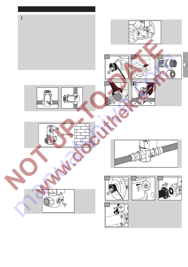
Installation position: black solenoid actuator in
the vertical upright position or tilted up to the
horizontal, not upside down.
> 20 mm
▷
The housing must not be in contact with masonry.
Minimum clearance 20 mm (0.79").
> 20 mm
▷
Sealing material and dirt, e.g. thread cuttings,
must not be allowed to get into the valve housing.
▷
Install a filter upstream of every system.
▷
Use approved sealing material only.
▷
Use a suitable spanner.
▷
Ensure that there is sufficient space for installa-
tion and adjustment.
▷
On VG 10/15 – 40/32, the inlet pressure p
u
can
be measured at the pressure test point.
p
u
p
u
p
d
▷
On VG 40 – 65, the inlet pressure p
u
and the
outlet pressure p
d
can be measured at the re-
spective pressure test point.
p
u
p
u
p
d
VG..R
2
3
1
4
Gas compression fittings
▷
The seals in some gas compression fittings
are approved for temperatures of up to 70°C
(158°F). This temperature limit will not be ex-
ceeded if the flow through the pipe is at least
1 m
3
/h (35.31 SCFH) of gas and the maximum
ambient temperature is 50°C (122°F).
VG..F
2
3
1
3


