

GB-2
D
GB
F
NL
I
E
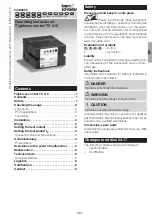
Checking the usage
TC 410 for tightness test before every controlled start-
up or after every controlled shut-down in systems
with 2 safety valves. Tightness control TC 410 can
be used for individual valves, quick opening or slow
opening with start gas rate. The valves are controlled
directly for testing by the TC 410. A pressure switch
for gas must be mounted on the interspace between
the valves to be monitored for the tightness test.
This function is only guaranteed when used within the
specified limits – see page 5 (Technical data). Any
other use is considered as non-compliant.
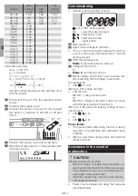
Type code
Code
Description
TC
Tightness control
4
In control cabinet
Testing before or after burner run
0
External pressure switch required
T
T-product
-
-0
Test period: 10 to 60 s
Test period: 100 to 600 s
K
N
T
Mains voltage: 24 V DC
110/120 V AC, 50/60 Hz
220/240 V AC, 50/60 Hz
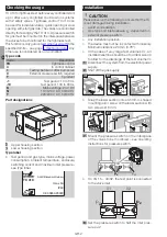
Part designations
OK
TEST
1
2
1
2
Upper housing section
Lower housing section
Type label
▷
Test period and gas type, mains voltage, power
consumption, ambient temperature, enclosure,
switching current and maximum inlet pressure –
see type label.
D-49018 Osnabrück, Germany
TEST OK
1
2
CE 0085AP0020
TC 410
Imax 5A
IP40
Installation
CAUTION
Please observe the following to ensure that the TC
is not damaged during installation:
– Avoid condensation.
– Gas type and inlet pressure p
u
: dependent on
external pressure switch.
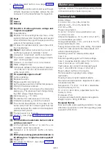
▷
Any installation position.
▷
The device must not be in contact with masonry.
Minimum clearance 20 mm (0.78").
▷
In the case of very large test volumes V
P
, an
installed relief line should be of nominal size 40
to allow for the discharge of the test volume V
P
.
Disconnect the system from the electrical power
supply.
Shut off the gas supply.
OK
TEST
1
2
1
2
70 (2.76")
21 (0.83")
37,5 (1.48"
)
ø 5 (ø 0.2")
4
3
5
6
6
▷
Snap the lower section onto a 35 mm U-shaped
mounting rail or screw on the lower section with
two screws Ø 5 mm.
OK
TEST
1
2
1
2
70 (2.76")
21 (0.83")
37,5 (1.48"
)
ø 5 (ø 0.2")
4
3
5
6
6
7
Mount the pressure switch on the interspace
of the valves to be monitored – see operating
instructions for pressure switch.
p
u
p
d
p
z
▷
On VG 15 – 40/32, the test point is connected
to the valve inlet.
V1
V2
p
u
p
z
8
Set the pressure switch to half the inlet pres-
sure p
u
/2.


