Krom Schroder DG 110VC Operating Instructions Manual Download Page 8

VAA · Edition 09.21

EN-8

Mechanical data

Gas types: clean air. The air must be clean and dry 
in all temperature conditions and must not contain 
condensate.
Medium temperature = ambient temperature.
CE  approved, max. inlet pressure p

u

: 500 mbar 

(7.25 psig).  
Flow adjustment limits the maximum flow rate to be-
tween approx. 20 and 100%.

Adjustment of the start rate: 0 to approx. 70%.

Opening times:  
VAA../N quick opening: ≤ 1 s;  
VAA../L slow opening: up to 10 s,  
VAA../R slow opening: 4 s. 
Closing time:  
VAA../N, VAA../L quick closing: < 1 s,  
VAA../R slow closing: 4 s. 
Switching frequency: VAA../N: max. 30 x per minute.
VAA../L, VAA../R: there must be a period of 20 sec-
onds between switching off and on again so that the 
damping is fully effective.
Valve housing: aluminium,  
valve seal: EPDM. 
Connection flanges:  
up to size 3: Rp internal thread to ISO 7-1, NPT to 

ANSI/ASME;  

size 2 and higher: with PN 16 ISO flange (pursuant 
to ISO 7005) . 
Cable gland: M20 x 1.5.
Electrical connection: cable with max. 2.5 mm

2


(AWG 12) or plug with socket to EN 175301-803. 
Duty cycle: 100%.
Power factor of the solenoid coil: cos φ = 0.9.
Recommended tightening torques for the connec-
tion parts:

Connection parts

tightening 

torque 

[ncm]

VAx 1: M5

500 ± 50

VAx 2: M6

800 ± 50

VAx 3: M8

1400 ± 100

electrical data

Mains voltage:  

230 V AC, +10/-15%, 50/60 Hz;  
200 V AC, +10/-15%, 50/60 Hz;  

120 V AC, +10/-15%, 50/60 Hz;  
100 V AC, +10/-15%, 50/60 Hz;  

24 V DC, ±20%. 

Power consumption:

type

Voltage

Power

VAA 1

24 V DC

25 W

VAA 1

100 V AC

25 W (26 VA)

VAA 1

120 V AC

25 W (26 VA)

VAA 1

200 V AC

25 W (26 VA)

VAA 1

230 V AC

25 W (26 VA)

VAA 2, 

VAA 3

24 V DC

36 W

VAA 2, 

VAA 3

100 V AC

36 W (40 VA)

VAA 2, 

VAA 3

120 V AC

40 W (44 VA)

VAA 2, 

VAA 3

200 V AC

40 W (44 VA)

VAA 2, 

VAA 3

230 V AC

40 W (44 VA)

Contact rating of position switch:

type

Voltage

Current (resistive 

load)

min.

max.

VAA..S

12–

250 V AC, 

50/60 Hz

100 mA

3 A

VAA..G

12–

30 V DC

2 mA

0.1 A

Switching frequency of position switch: max. 5 x per 
minute.

switching 

current

switching cycles*

cos φ = 1

cos φ = 0.6

0.1

500,000

500,000

0.5

300,000

250,000

1

200,000

100,000

3

100,000

* Limited to max. 200,000 cycles for heating systems.

Summary of Contents for DG 110VC

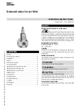
Page 1: ...ust be installed and commissioned in accordance with the regulations and standards in force These instructions can also be found at www docuthek com Explanation of symbols 1 2 3 a b c Action Instruction Liability We will not be held liable for damage resulting from non observance of the instructions and non com pliant use Safety instructions Information that is relevant for safety is indicated in ...

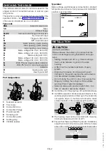
Page 2: ...e electrical power consumption ambient temperature enclosure inlet pressure and installation position see type label Elster GmbH Osnabrück Germany Vxx XXXX INSTALLATION CAUTION Incorrect installation Please observe the following to ensure that the unit is not damaged during installation and oper ation Sealing material and dirt e g thread cuttings must not be allowed to get into the valve housing A...

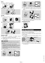
Page 3: ...ng Fig c must be fitted d e Note the recommended tightening torques for the connection parts See page 7 Technical data f g WIRING WARNING Risk of injury Please observe the following to ensure that no damage occurs Electric shocks can be fatal Before working on possible live components ensure the unit is disconnected from the power supply The solenoid actuator heats up during operation Surface temp...

Page 4: ...ier the connection terminal for the position switch can be removed 1 3 2 LV1 N 1 COM 2 Valve open Valve closed 3 1 3 2 LV1 N 1 COM 2 Valve open Valve closed 3 When installing two plugs on VAA a with position switch label the sockets and plugs to avoid con fusion 2 1 3 2 1 1 COM 2 Valve open Valve closed 3 Ensure that the connection terminal for the position switch has been reconnected Finishing th...

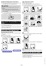
Page 5: ... Q The markings on the cover cap can be used for coarse adjustment of the flow rate The cover cap can be rotated without changing the current flow rate Allen key 2 5 mm Do not turn beyond the max setting Q max min 100 0 U min max The VAA remains tight even if the adjusting screw is overturned Setting the start rate on the VAA L The start rate can be set by turning the damping unit a maximum of 5 t...

Page 6: ...pply 2 Shut off the air supply Loosen the M3 setscrews 1 5 mm hexagon sock et but do not unscrew completely 3 M3 4 5 6 M3 7 Set the start gas rate see page 5 Setting the start rate on the VAA L Slow opening slow closing 1 Shut off the air supply The solenoid actuator remains switched on Loosen the M3 setscrews 1 5 mm hexagon sock et but do not unscrew completely 2 M3 3 4 5 Switch off the solenoid ...

Page 7: ...x setting mbar WC mbar WC DG 17VC 2 17 0 8 6 8 0 7 1 7 0 3 0 8 DG 40VC 5 40 2 16 1 2 0 4 1 DG 110VC 30 110 12 44 3 8 0 8 3 2 DG 300VC 100 300 40 120 6 15 2 4 8 Deviation from the switching point during testing pursuant to EN 1854 Gas pressure switches 15 Variable bypass VAA B For retrofitting on the VAA the bypass can be supplied as an additional item Order No 74926325 1 Shut off the air supply Us...

Page 8: ...onnection cable with max 2 5 mm2 AWG 12 or plug with socket to EN 175301 803 Duty cycle 100 Power factor of the solenoid coil cos φ 0 9 Recommended tightening torques for the connec tion parts Connection parts Tightening torque Ncm VAx 1 M5 500 50 VAx 2 M6 800 50 VAx 3 M8 1400 100 Electrical data Mains voltage 230 V AC 10 15 50 60 Hz 200 V AC 10 15 50 60 Hz 120 V AC 10 15 50 60 Hz 100 V AC 10 15 5...

Page 9: ...all service life will be reduced by the corresponding amount of extra storage time CERTIFICATION Declaration of conformity We the manufacturer hereby declare that the prod ucts VAA comply with the requirements of the listed Directives and Standards Directives 2014 35 EU LVD 2014 30 EU EMC 2011 65 EU RoHS II 2015 863 EU RoHS III Standards based on EN 161 Elster GmbH Scan of the Declaration of confo...

Page 10: ...ipse Exothermics Hauck Kromschröder and Maxon To learn more about our products visit ThermalSolutions honeywell com or contact your Honeywell Sales Engineer Elster GmbH Strotheweg 1 D 49504 Lotte T 49 541 1214 0 hts lotte honeywell com www kromschroeder com Global centralized service deployment coordination T 49 541 1214 365 or 555 hts service germany honeywell com Translation from the German FOR ...

Reviews: