background image

 INSTALLATION 

2

9

OPTIWAVE-M 7400

www.krohne.com

10/2018 - 4007039501 - AD ATEX OPTIWAVE-M 7400 R01a

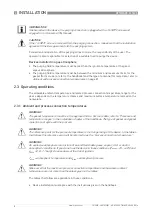
Make sure that the device temperature does not increase because of other heat sources 
(sunlight, adjacent system components etc.). The device must not be operated above the 
maximum permitted ambient temperature.

Do not put insulation around the signal converter. Make sure that the airflow around the 
signal converter is sufficient. It is permitted to have insulation on the pipe or stilling well and 
the process connection.

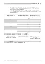
Temperature class for 

EPL Ga/Gb,  EPL Gb  or  EPL Gc

Maximum ambient temperature

Maximum process connection 

temperature

(max. process temperature)

[

°

C]

T6

+60

+60

+53

+85

T5

+75

+75

+68

+100

T4

 1

+71

+115

+65

+135

T3

 2

+62

+150

+54

+180

+49

+200

1

Max. process connection temperature is +100

°

C, if the device has a PP Drop antenna

2

Max. process connection temperature is +150

°

C, if the device has a PTFE Drop antenna

Temperature class for 

EPL Ga/Gb,  EPL Gb  or  EPL Gc

Minimum ambient temperature

Minimum process connection 

temperature

(min. process temperature)

[

°

C]

All classes

 1

-40

-40

1

Min. process connection temperature is -20

°

C, if a Kalrez

®

 gasket is used

Summary of Contents for OPTIWAVE-M 7400

Page 1: ...nstructions for ATEX applications Supplementary Instructions for ATEX applications OPTIWAVE M 7400 OPTIWAVE M 7400 OPTIWAVE M 7400 OPTIWAVE M 7400 Supplementary Instructions Supplementary Instructions...

Page 2: ...onnections 10 3 1 General notes 10 3 2 Terminal compartment 11 3 2 1 How to open the terminal compartment 11 3 2 2 How to close the terminal compartment 12 3 3 Terminal tightening capacity 12 3 4 Equi...

Page 3: ...nal 1 3 Standards and approvals You can download the certificate from our internet site INFORMATION The information in these supplementary instructions only contains the data applicable to explosion p...

Page 4: ...plications requiring Category 1 2 G and EPL Ga Gb or Category 2 G and EPL Gb equipment when fitted with the appropriate options It agrees with temperature classes T6 thru T1 Gas Groups if the temperat...

Page 5: ...on including approved Gas Groups and temperature classes and equipment protection level 3 Intrinsically safe circuit data Refer to 7 for the input voltage range 4 WARNING Potential electrostatic charg...

Page 6: ...crease in electrostatic charge caused by compressed air and dust locations near machines that use friction locations near systems that apply electrons as a spray e g near electrostatic painting system...

Page 7: ...ntennas DANGER Make sure that the device and adjacent objects do not rub together Make sure that all personnel and equipment are correctly grounded If dirt collects on the device clean it with a damp...

Page 8: ...he instructions given in the handbook INFORMATION If delivered with the device the purging connection is plugged with a 1 4 NPTF screw and engaged on a minimum of 3 threads CAUTION If the 1 4 NPTF scr...

Page 9: ...pe or stilling well and the process connection Temperature class for EPL Ga Gb EPL Gb or EPL Gc Maximum ambient temperature Maximum process connection temperature max process temperature C T6 60 60 53...

Page 10: ...e com 10 2018 4007039501 AD ATEX OPTIWAVE M 7400 R01a 3 1 General notes WARNING De energize the circuit Use the applicable cable glands for the cable entry openings in the housing M20 1 5 or M25 1 5 F...

Page 11: ...Use the 3 mm Allen wrench to remove the cover stop Use the wrench to remove the cover For more data about the procedure refer to the handbook WARNING Do not blow dust with compressed air if it collect...

Page 12: ...a slot on the top of the cover is correctly aligned with the hole for the cover stop Attach the cover stop make sure that there is also a spring washer and a socket head screw Tighten the screw with...

Page 13: ...tection IP 68 Make sure that the cable gland is sealed Obey the instructions that follow Electrical wires must agree with applicable standards e g EN 60079 14 Use the electrical connection procedure i...

Page 14: ...for the level transmitter to terminal and If your device has the optional pressure transmitter connect electrical wires from the pressure transmitter to terminal A and B Output Intrinsically safe val...

Page 15: ...system correctly Are you using intrinsically safe barriers within the correct parameters For more data refer to Maximum intrinsically safe values for the electrical circuit on page 14 The electrical c...

Page 16: ...nnection make sure that the tank is not pressurized A pressurized tank can cause injury to persons when they do work on it Make sure that all electrical wires are isolated from the ground This is also...

Page 17: ...the signal converter the data temperature voltage etc given in these supplementary instructions agrees with the new device configuration 5 5 Manufacturer KROHNE S A S 2 All e des Ors B P 98 26103 Roma...

Page 18: ...arding the health and safety of the personnel the manufacturer may only handle test and repair returned devices that have been in contact with products without risk to personnel and environment This m...

Page 19: ...rtment Name Tel no Fax no and or Email address Manufacturer s order no or serial no The device has been operated with the following medium This medium is radioactive water hazardous toxic caustic flam...

Page 20: ...es Head Office KROHNE Messtechnik GmbH Ludwig Krohne Str 5 47058 Duisburg Germany Tel 49 203 301 0 Fax 49 203 301 10389 info krohne com KROHNE 10 2018 4007039501 AD ATEX OPTIWAVE M 7400 R01a en Subjec...

Reviews: