Installation and Operating Instructions
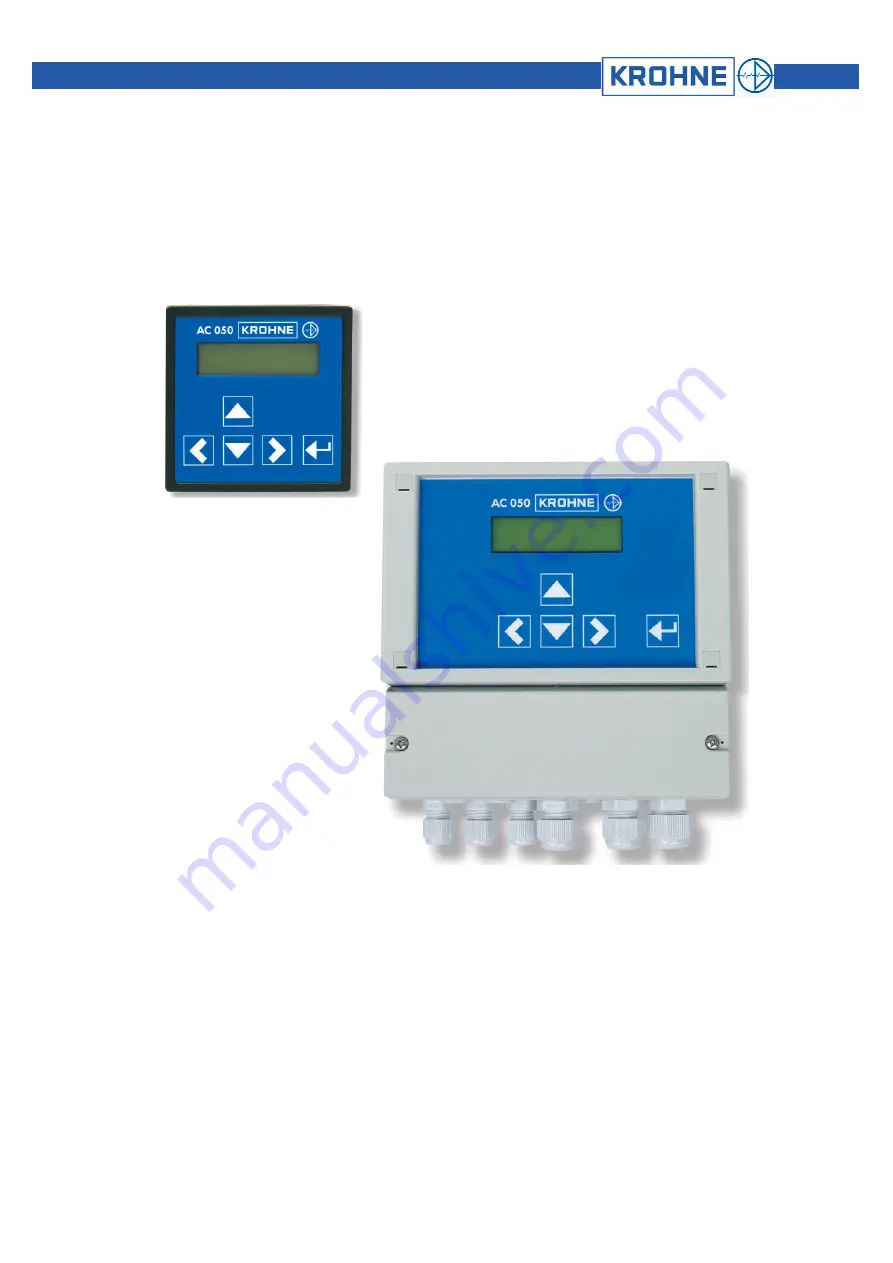
OPTISENS AAC 050
Measuring and control instruments for potentiostatic measurements of Chlorine, total Chlorine, Chlorine dioxide, Oxygen, Ozone and Hydrogen peroxide
07/2008
Page 1: ...llation and Operating Instructions OPTISENS AAC 050 Measuring and control instruments for potentiostatic measurements of Chlorine total Chlorine Chlorine dioxide Oxygen Ozone and Hydrogen peroxide 07...
Page 2: ...ion of the converter 15 4 2 Calibration 15 4 3 Temperature compensation 16 4 3 1 Calibration of the temperature measurement 16 4 4 Automatic Sensor Cleaning ASR option 17 5 Adjustments of the controll...
Page 3: ...Manual OPTISENS AAC 050 3 OPTISENS AAC 050 9 2 1 Panel mounting enclosure 30 9 2 2 Wall mounting enclosure 30 10 Device return form 31 11 Customer settings for reference 32...
Page 4: ...le and Delivery found on the back of the invoice and forming the basis of the purchasing contract are applicable General limitation on liability Unless otherwise expressly set forth in the Standard Te...
Page 5: ...safe usage follow all instructions carefully and pay special attention to all warnings issued in this manual If the device is visibly damaged or has been stored inappropriately or if there are any dou...
Page 6: ...ntroller types ON OFF controller with hysteresis P controller as Pulse Pause Impulse Frequency or steady controller PI controller as Pulse Pause Impulse Frequency or steady controller Hysteresis adjus...
Page 7: ...r by sliding the slot under a screw which is an alternative for limited space Either way you have to fix it additionally with two screws ATTENTION Install the device in a place where it is not put und...
Page 8: ...upon the upper screw In that case drill the upper hole 120mm 4 7 above the lower two 2 Or you can slip the fixture on the back of the device under the upper screw In that case the upper hole has to be...
Page 9: ...ly The potentiostatic measurement is interference sensitive especially when using membrane sensors Use a special screened cable Membrane sensors are delivered complete with cable When using the relays...
Page 10: ...lectrode sensors bridge 3 4 1 2 measurement 3 6V Membrane Sensor with electronics 1 4 4 6V Pt100 NTC 5 6 Analog output 9 10 9 10 max burden 500 Ohm Digital input 11 12 11 12 external controller stop o...
Page 11: ...ement 3 6V Membrane sensors with electronics 1 4 4 6V Pt100 NTC 6 7 Display contrast Display Potentiometer to adjust the display contrast Analog output 11 12 11 12 max burden 500 Ohm Relay 1 14 15 Rel...
Page 12: ...ring With key Enter changes are stored For your convenience arrows in the display indicate the directions you can take from your position in the menu 3 1 How to adjust parameters Temp comp Manual 1 Wh...
Page 13: ...mp Temperature compensation only for pH measurements Enter password Password function Set points Controller settings set points P ranges I functions Limit values Alarm function Basic settings Basic se...
Page 14: ...anual compensation Flow rate Display of the flow measurement Basic settings Basic settings Cal Pt NTC Calibration of the temperature measurement Flow rate Calibration of the flow measurement Flow alar...
Page 15: ...peroxide H2O2 0 0 100 0 mg l Input 2 works with the temperature sensors Pt100 or NTC 4 2 Calibration Main menu Calibration DPD Calibration DPD Calibration 0 48 mg l Slope Enter the concentration dete...
Page 16: ...nual Temp 25 0 C Basic settings Calibration Pt 100 NTC Basic settings Cal Pt 100 NTC Cal Pt 100 NTC 0 0 C Temp coefficient Temp coeff Temp coeff 0 0 K Select between two ways of compensation 1 Automat...
Page 17: ...last measured value for five minutes and the message cleaning in progress is displayed As a safety measure attempts to calibrate within these five minutes are ignored Activation and timing The cleani...
Page 18: ...eved by either reducing the switch frequency Impulse frequency controller or reducing the time within a given period of time in which the relay is ON pulse pause controller The parameters for a P cont...
Page 19: ...nu Set points and controller version Set points Set point S1 You can choose different 1 50 mg l Controller versions P range S1 For S1 and S2 0 20 mg l Integral time S1 000 sec Set point S2 0 50 mg l C...
Page 20: ...pulse pause controller you have to set the following parameters 1 Set points S1 and S2 S1 refers to relay 1 S2 refers to relay 2 2 P range and integral action time Adjust a P range 0 For a P controll...
Page 21: ...y Turn on delay Turn on delay OFF ON Turn on delay 180 s 5 5 Turn on delay Set a delay time which has to pass before the controller is activated after start up or power interrupt This allows the measu...
Page 22: ...1 402 mS 25 0 C S1 S2 Man 6 Switch ON relay 2 with key The square to the left of S2 gets dark 1 402 mS 25 0 C S1 S2 Man 7 Switch OFF relay 2 again with key The square gets light 1 402 mS 25 0 C S1 S2...
Page 23: ...s it happens regularly that the measured value exceeds a limit for a short period of time To avoid having an alarm issued under these circumstances you can adjust a turn on delay which has to pass bef...
Page 24: ...of calibration failure the controller is not deactivated to enable you to continue the dosing or treatment process until a replacement sensor is at hand Sensor check during measurement During measure...
Page 25: ...e sensor was used Limit 1 2 The measured value exceeded limit 1 or dropped below limit 2 respectively Please check the dosing and readjust the control parameters if necessary Dosage check 1 2 Controll...
Page 26: ...g 4 20 mA the resolution is lower but defective cable connections are immediately evident With the parameters Begin and End you define which part of the measuring range you want to read out Alternativ...
Page 27: ...a Bayonet lock Turn the lock to the left until the fuse pops up Exchange it and fix the new fuse by turning the lock to the right Put the front back on and fix it tightly WARNING Disconnect the power...
Page 28: ...tion of the device hardware and software 8 7 2 Analog inputs Here you can see the raw data the device obtains from the sensors They are not influenced by compensations or calibration and offer valuabl...
Page 29: ...ature with dimensions indication of relay status Current outputs 2 x 0 4 20 mA galvanically isolated max loading 500 Ohm Interface option RS485 Baud rate 9600 data format 8Bit 1 Start and 1 Stop bit C...
Page 30: ...Manual OPTISENS AAC 050 OPTISENS AAC 050 30 9 2 Dimensions 9 2 1 Panel mounting enclosure 9 2 2 Wall mounting enclosure...
Page 31: ...firming that the device is safe to handle If the device has been operated with toxic caustic flammable or water endangering products you are kindly requested to check and ensure if necessary by rinsin...
Page 32: ...or conductivity for Temperature Controller S1 Controller S2 Controller S1 Controller S2 Start Start End End Controller Controller S1 Controller S2 Acting direction Acting direction raise lower raise l...