


4
TECHNICAL DATA
18
BATCHFLUX 5500 C
www.krohne.com
05/2014 - 4003386301 - QS BATCHFLUX 5500 R03 en
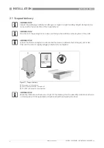
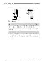
4.2 Counter Flanges
The BATCHFLUX 5500 can be mounted between various types of counter flanges.
Sizes of flanges
Note; flanges must be fully welded and surface roughness, grinded and polished ( roughness
0,8). See for more information the 3A CCE 2007-2 Coordination Bulletin.
DN
a [mm]
b [mm]
c [mm]
d [mm]
O-ring
Flange
1
2,5...10
* see table
below
* see table below
* see table
below
Ø 30.4
Special L-
ring
Flange
2
15
Ø 14.2
Ø 19.2
Ø 26.6
Ø 30.4
15.47 *
3.53
Flange
3
25
Ø 25
Ø 31.3
Ø 41.2
Ø 49.2
15.47 *
3.53
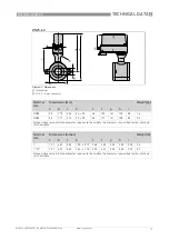
Size DN
a
1
[mm]
a
2
[mm]
b [mm]
c [mm]
2,5
Ø 10
Ø 6.2
Ø 11.1
Ø 18.4
4
Ø 10
Ø 7.2
Ø 12.1
Ø 19.4
6
Ø 10
Ø 9.2
Ø 14.2
Ø 21.5
10
Ø 10
Ø 10.7
Ø 15.7
Ø 23
INFORMATION!
The O-rings require periodic inspection and replacement. As the interval depends on process-
specific variables, the length of the interval cannot be specified.
The O-rings are not part of the portfolio of KROHNE.
INFORMATION!
For 3A applications, O-rings must conform to the requirements of the 3A sanitary standard for
Flow meters, number 28-04 Class I or Class II (max. 8% milk fat).
The used O-rings must also withstand the processing, sterilization and chemical conditions for
the intended use ( for more information, contact the manufacturer)


