background image

Installing Your Monitors

The close-field monitor, by definition, reduces room interaction. This can be com-
pared to the conventional stereo configuration or the large monitor arrangement in
a recording studio where sounds emanating from the monitor or reflecting off ceil-
ings, walls, and floors greatly affect the sound quality. By shortening the path to the
ear, the close-field monitor offers a tremendous amount of flexibility, allowing the
sound to become less susceptible to differing room conditions. The ability to adjust
the high and low frequency characteristics is equally important to help compensate
for room irregularities and achieve the highest sound accuracy.

(See HF Adjustments

sections on page 2. Note- These adjustments are only available on the Rokit Powered Series.)

A room that is heavily dampened would typically require a high frequency boost.
Likewise, reducing the high frequencies can alter a reverberant room. The low fre-
quency can be adjusted to compensate for the first reflection (bounce) off the
woofer, whether it comes from the floor, as in the typical stereo setup, or from the
surface of the mixing board (when the monitor is placed atop the meter bridge).

Placing the monitor close to a rear wall, sidewall, or a corner will reinforce the low
frequencies. Generally speaking, if you move them two to three feet away from
walls and corners, you'll hear less low frequency interaction (excluding any interac-
tion with the mixing console). But when ideal positioning isn't practical, low frequen-
cy control is the solution. Lets say you have two different studios in your facility; in
one room the monitors are close to the wall, in the other they're further away from
the wall. Simply adjust the low frequency on each monitor and you'll have the same
sound in each room. This comes in handy if you're tracking in room A and mixing
down in room B.

Positioning Your Monitors

Positioning your monitors correctly in the studio is critical to their performance.
Typically, they should be placed so that that the listening position is fully "covered"
with all monitors resting on the same horizontal plane. A great way to test a monitor
for its imaging capability is to play back a CD or DVD recorded acoustically in
stereo (or one recorded in surround sound if you have a surround sound set-up).
We recommend acoustic music because it represents the spectrum of sound.)  You
can adjust the angle of each monitor by listening for dead spots. Keep in mind,
changing the angle or position of a monitor will change the sound.
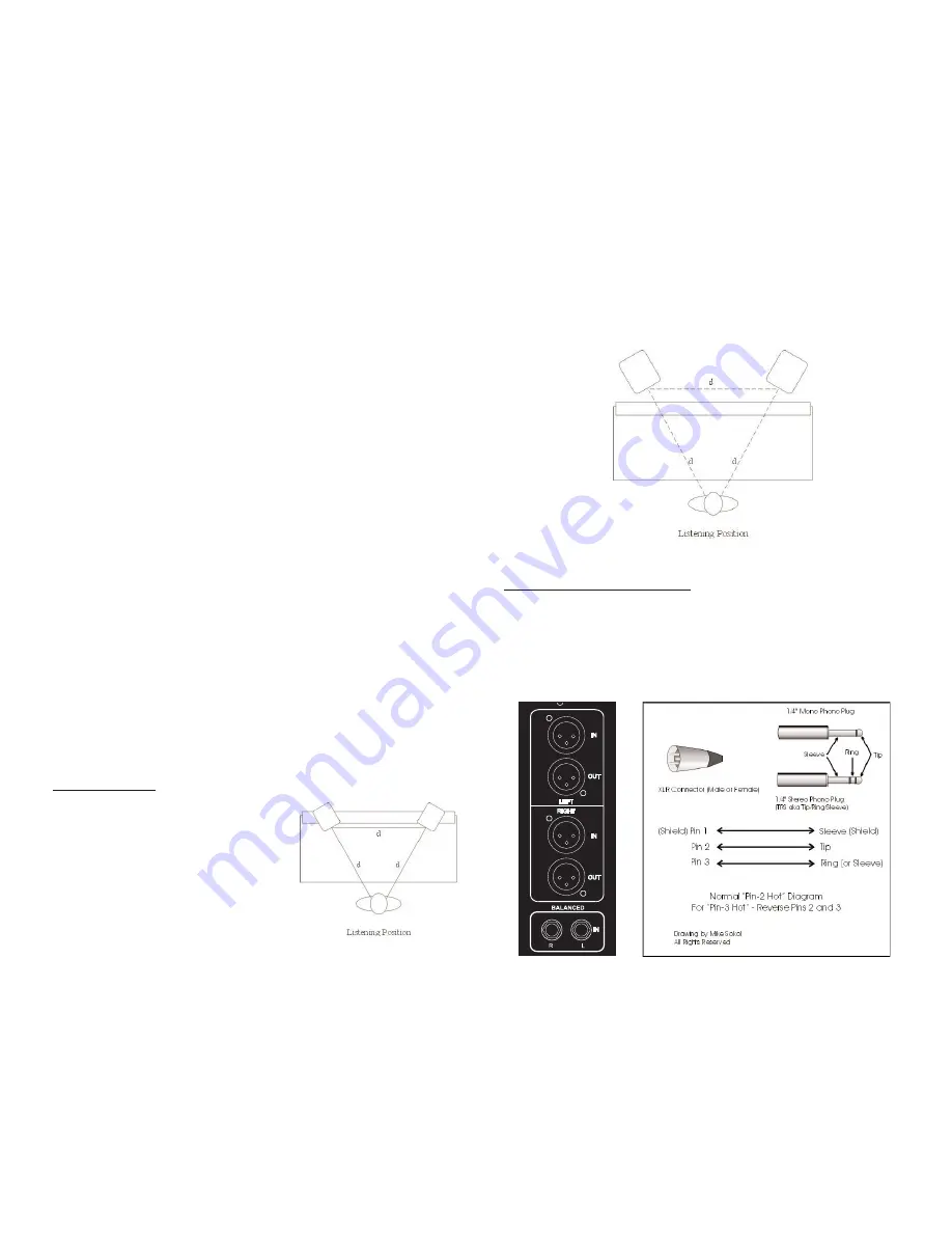
2-CHANNEL SET-UP

Close-Field Configuration - In a control room situa-
tion, the monitors are often times placed on the
meter bridge or in a close-field listening position.
Initial placement starts by measuring out a simple
equilateral triangle (all three sides equal in length)
with the apex at the center of the listening position
(as shown in Figure 1) as an "overlay" for the
stereo installation. In this configuration, the Left
and Right monitors are each placed at a 60º angle
equidistant from the listening position.

Mid-Field Configuration

– This configuration is basically the same as the Close-

Field set-up.  (see Figure 2)  It is normally used with larger monitors or when the
monitors are too large or heavy for the meter bridge. This set-up has the potential
for a larger sweet spot and better spatial imaging.  Make sure that the height of the
woofer is above height of the console. 

Hooking Up Your Subwoofer: Stereo Systems

Hooking Up Your Subwoofer (Stereo)

The KRK subwoofers include a built-in crossover and amplifier, so you only need
the appropriate hookup cables to integrate it into your existing monitor system.
First, you need to connect a pair of cables from the stereo monitor outputs of your
console to the left and right XLR, 1/4” or RCA input jacks on the subwoofer.

Next, if you are using the internal 80-Hz high-pass filter built into the subwoofer for
the existing full-range monitors (and most of you will), hook the XLR, 1/4” or RCA
output jacks on the subwoofer to the line-level inputs of your full-range speaker

7

8

Figure 1

Figure 2 

Summary of Contents for ROKIT POWERED SERIES

Page 1: ...O MONITOR SUBWOOFER GUIDE KRK SYSTEMS LLC 9340 De Soto Ave Chatsworth CA 91311 USA HTTP WWW KRKSYS COM PART LITK00017 Our mission is to innovate design and deliver superior audio products that form the bridge between an artistic vision and a realized dream ...

Page 2: ...h the same characteristics as the original parts have been used and that the routine safety checks have been performed to guarantee that the equipment is in safe operating condition REPLACEMENT WITH UNAUTHORIZED PARTS MAY RESULT IN FIRE ELECTRIC SHOCK OR OTHER HAZARDS ATTENTION POUR VITER LES CHOC ELECTRIQUES INTRODUIRE LA LAME LA PLUS LARGE DE LA FICHE DANS LA BORNE CORRESPONDANTE DE LA PRISE ET ...

Page 3: ...materials Please save these items They should be used when trans porting or shipping your Rokit Powered monitors Unpacking Your Rokit Powered subwoofer has been carefully inspected and tested before packing and shipping After unpacking your monitor subwoofer carefully inspect it for exterior damage and immediately report any physical damage during transit to your shipping carrier Save the shipping...

Page 4: ...cers we ve come to understand how a properly tuned monitor can become a valuable recording tool 2 Distortion Management Physical Non linear and Electronic Distortion Any deviation of the original audio signal is a distortion Various amplifier distortions have been identified the most commonly measured being intermodula tion and harmonic distortion Distortion can be present in an amplifier circuit ...

Page 5: ...low LED illuminates the trademarked KRK Triangle on the front baffle when power is applied NOTE MAKE SURE THAT THE VOLTAGE INDICATOR FOUND IN THE VOLTAGE SELECTOR IS SET TO THE CORRECT VOLTAGE SETTING FOR YOUR VOLTAGE CHANGING VOLTAGE To change the voltage remove the power cord slide voltage selector to desired voltage setting Please note when making voltage changes the fuses will have to be repla...

Page 6: ...tudio is critical to their performance Typically they should be placed so that that the listening position is fully covered with all monitors resting on the same horizontal plane A great way to test a monitor for its imaging capability is to play back a CD or DVD recorded acoustically in stereo or one recorded in surround sound if you have a surround sound set up We recommend acoustic music becaus...

Page 7: ...bwoofer you run the risk of damaging the equip ment Rotate the subwoofer s gain control counterclockwise and set the low pass filter control to the 80Hz position Power up the subwoofer prior to the other speakers shut down in reverse order note that the power light is illuminated Play back some music and turn the console output up to a moderate listening volume At this point the bass should sound ...

Page 8: ...er placement within the room and 2 via electrical settings that affect levels low pass filter frequency and phase Proper Physical Placement of Subwoofer Just because bass frequencies are largely non directional does not mean that you can ignore the subwoofer s placement in the room If fact a sub s physical position in the room in relation to the floor walls and other surfaces radically influences ...

Page 9: ...500 Hz to 2 000 Hz for the near field speakers After adjusting each near field speaker one at a time to 85 dB SPL adjust the LFE channel 10 dB louder or 95 dB SPL Use the LFE level trim for this adjustment rather than the subwoofer gain control which would corrupt the sub woofer bass management levels set in the previous section Bass Management Theory Bass Management Bass management is a method fo...

Page 10: ...ed to the dealer that you purchased it from or to KRK for servicing Problem The sound quality changes Repeat steps in the previous troubleshooting section above before continuing to the next steps Disconnect the signal cable at the input of the monitor With power on place your ear close to each driver tweeter woofer and listen for noise i e a slight hiss or hum If there s absolutely no sound whats...

Page 11: ...Connector System Volume Control LED Power Indicator RP5 53Hz 20kHz 2 0dB 1 Soft Dome 5 Aramid Glass Fiber 10 7 8 x 7 1 4 x 8 7 8 28 cm x 19 cm x 23 cm 16 lbs 15 watts 30 watts 82dB 90dB 05 02 10K Ohm 10K Ohm 3 0KHz 45Hz 1A 500mA RP6 49Hz 20kHz 1 5dB 1 Soft Dome 6 Aramid Glass Fiber 12 11 16 x 8 7 8 x 10 1 2 38 cm x 27 cm x 31 cm 23 lbs 18 watts 50 watts 84dB 95dB 09 01 10K Ohm 10K Ohm 2 6KHz 40Hz ...

Reviews: