background image

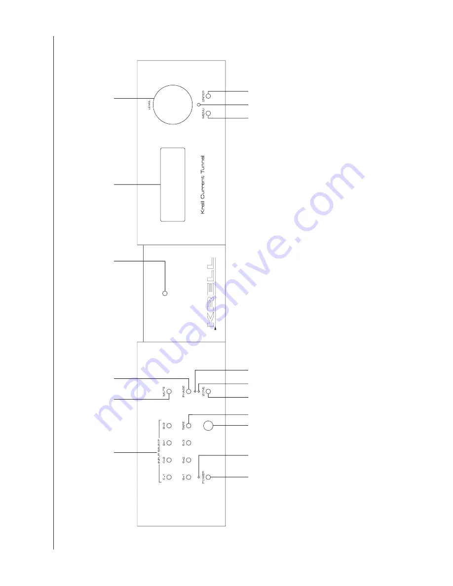
Figure 1 The KCT Front Panel

Power

1 Power Button

2 Stand-by LED

3 Power LED

Remote Control Functions

4 Infrared Sensor

5 Infrared 

T

ransmitter LED

1

Preamplifier Functions

6 Input Select Buttons

7 T

ape 

Button

8 Mute Button

9 Phase Button 

10 Zone Button 

1

1

 Main Zone LED

12 Zone 2 LED

Display

13 Front Panel Display 

Level Control

14 Level Control Knob

Menu Functions

15 Menu Button

16 Enter Button

69

1

3

14

1

4

5

27

3

10

11

12

16

15

8

KCT

CLASS A

Summary of Contents for KCT

Page 1: ...KCT Krell Current Tunnel CAST Preamplifier Instructions for Use Owner s Reference THE LEADER IN AUDIO ENGINEERING ...

Page 2: ...e EMC directive 89 336 EEC and the low voltage directive 73 23 EEC WARNINGS The preamplifier must be placed on a firm level surface where it is not exposed to dripping or splashing The ventilation grids on the top of the preamplifier and the space underneath the preamplifier must be unobstructed at all times during operation Do not place flammable material above or beneath the preampli fier Before...

Page 3: ...ONNECTING THE KCT PREAMPLIFIER TO YOUR SYSTEM 18 Input and Output Connections 18 KRELL LINK CONNECTIONS AND OPERATION 19 TAPE INPUT AND OUTPUT 20 OPERATING THE KCT PREAMPLIFIER 21 On Off and Stand by Operation 21 Main Zone and Zone 2 Operation 22 TROUBLESHOOTING SYSTEM NOISE 25 CUSTOMIZING THE KCT PREAMPLIFIER 26 Z1 and Z2 Balance 26 Input Name Menu 26 Input Level Trim 27 Input Balance Trim 27 The...

Page 4: ...ut Trigger Setup 31 Setup Memory 32 Krell Link 32 Trigger Delay Setup 33 Exit Menu 33 QUESTIONS AND ANSWERS 34 WARRANTY 35 RETURN AUTHORIZATION PROCEDURE 36 SPECIFICATIONS 37 List of Illustrations Figure 1 The KCT Front Panel 8 Figure 2 The KCT Back Panel 11 Figure 3 The KCT Remote Control 14 ...

Page 5: ...provides feedback on input and zone status menu function and selection and all preamplifier operations This owner s reference manual contains important information on the placement installation and operation of your KCT preamplifier Please read this information carefully A thorough understanding of these details will help ensure satisfactory operation and long life for your KCT and related system ...

Page 6: ... making or breaking single ended connections Single ended connections are not recommended for connections requiring long cable runs OPERATION Off When the power button on the front panel is pressed and the blue power LED turns off the component is off Operational Mode When the power button on the front panel is pressed and the blue power LED illuminates the component is in the operational mode and...

Page 7: ...itry This current signal is then output using CAST circuitry When the signal is received by a CAST input Krell Current Mode circuitry again takes over until the signal reaches the loudspeaker By maintaining the musical signal in the current domain from beginning to end an entire CAST system behaves as if it is one component With CAST anomalies of signal transmission between components are eliminat...

Page 8: ...rmance area speed precision dynamic range depth and width of the sound stage transient impact tonal balance harmonic distortion and more The goal for CAST is the same company goal used for all Krell products Krell strives for the delivery of the best performance of a musical event for you using the full expression of technology to date ...

Page 9: ...t transit damage See Return Authorization Procedure on page 36 Placement Before you install the KCT preamplifier into your system review the following guidelines to select the location for your component This will facilitate a clean trouble free installation The KCT does not require a special rack or cabinet for installation See Specifications on page 37 for the dimensions of the KCT The KCT requi...

Page 10: ...nts to CAST inputs or outputs can damage your equipment and void your warranty Do not attempt to alter CAST cable ends or CAST inputs or outputs It is electrically impossible to convert CAST input output chassis mount connectors for balanced or single ended operation Please read the Warranty on page 35 to understand the warranty limitations of the KCT 3 Connect the CAST 23 balanced or single ended...

Page 11: ...he remote control Start playing the source Use the level control knob 14 or level keys 44 to set the volume to a comfortable listening level Note The KCT automatically plays through the main zone until you select zone 2 operation 3 To return the KCT to the stand by mode press the power button 1 or power key 32 Krell recommends leaving the KCT in the stand by mode when it is not playing music If yo...

Page 12: ...nfrared Transmitter LED 1 Preamplifier Functions 6 Input Select Buttons 7 Tape Button 8 Mute Button 9 Phase Button 10 Zone Button 11 Main Zone LED 12 Zone 2 LED Display 13 Front Panel Display Level Control 14 Level Control Knob Menu Functions 15 Menu Button 16 Enter Button 6 9 13 14 1 4 5 2 7 3 10 11 12 16 15 8 KCT CLASS A ...

Page 13: ...ontrol For proper remote control operation make sure the infrared sensor is not covered or obstructed 5 Infrared Transmitter LED The infrared transmitter LED flashes when the KCT sends infrared signals to another remote control See Program Remote Menu on page 31 Preamplifier Functions 6 Input Select Buttons Use these buttons to select the corresponding rear panel input that is connected to a CAST ...

Page 14: ...ctivated Zone status is also shown in the front panel display 13 Display 13 Front Panel Display The front panel display provides preamplifier status messages including input and zone selection tape output status volume and balance level and menu selections Level Control 14 Level Control Knob Use this knob to increase or decrease system volume level or with the balance key to adjust balance The lev...

Page 15: ...pe Output 21 Tape Output Main Zone Outputs 22 Preamp Left and Right Outputs 23 CAST Preamp Outputs Zone 2 Outputs 24 Balanced Left and Right Outputs 25 Single ended Left and Right Outputs Back Panel Remote Control Inputs and Outputs 26 Krell Link In and Out 27 12 VDC In and Out 28 RC 5 In 29 RS 232 Phono Stage Connector 30 Phono Power Power 31 IEC Power Connector 17 20 21 22 23 26 28 27 19 18 30 2...

Page 16: ... C 1 and C 2 Left and Right CAST Inputs The KCT is equipped with two pairs of CAST inputs with 4 pin bayonet connectors for use with Krell CAST equipped input devices Tape Output 21 Tape Left and Right Outputs The KCT is equipped with one pair of tape outputs with RCA connectors Main Zone Outputs The following outputs are for the main zone 22 Preamp Left and Right Outputs The KCT is equipped with ...

Page 17: ...ts through the 12 V trigger it sends a signal that will switch other components allowing whole systems or parts of systems to be easily coordinated Notes The 12 VDC output power is limited to 30 ma Consult the owner s reference manual of the components used in a custom installation to take full advantage of the remote capabilities of the KCT 28 RC 5 In The KCT is equipped with an RC 5 input that m...

Page 18: ...ey 38 Z2 Key 39 Input Select Keys 40 Tape Key Menu Functions 41 Menu Key 42 Enter Key Level Control 43 Bal ance Key 44 Level Keys Compact Disc Functions 45 Pause Key 46 Stop Key 47 Play Key 48 Track Forward and Back Keys 49 Search Forward and Back Keys Power 32 Power Key Amplifier Functions 33 Amp Pwr Key 34 Amp Sel ect Key 14 Krell Current Tunnel ...

Page 19: ...ions Remote control keys and their descriptions follow Power 32 Power Key Use this key to switch the KCT between the stand by and the operational modes Amplifier Functions 33 Amp Pwr Key Use this key to activate Krell amplifiers connected to your system The amp pwr key also activates the control component for amplifiers connected by Krell Link 34 Amp Sel ect Key Use this key to switch between CAST...

Page 20: ...put that is connected to a tape analog source When TAPE is activated the front panel display 13 shows the zone that is the pathway for the tape output See Tape Output Menu on page 30 Menu Functions 41 Menu Key Use this key to access the menu options for customizing the KCT The front panel display 13 shows MAIN MENU and submenu name See Customizing the KCT Preamplifier on page 26 42 Enter Key Use t...

Page 21: ...again or press the play key 47 46 Stop Key Use this key to end compact disc playback 47 Play Key Use this key to begin compact disc playback 48 Track Forward and Back Keys Use these keys to select and begin playing the track that follows or precedes the current track 49 Search Forward and Back Keys Press and hold these keys to scroll forward or backward through the current track Note For informati...

Page 22: ...not attempt to alter CAST cable ends or CAST inputs or outputs It is electrically impossible to convert CAST input output chassis mount connectors for balanced or single ended operation Follow these steps to connect the KCT preamplifier to your system 1 Neatly arrange and organize the wiring to and from the KCT and all components Separate AC wires from audio cables to prevent hum or other unwanted...

Page 23: ... Connect one end of the MIDI cable to the Krell Link out connector 26 on the control component back panel 4 Connect the other end of a MIDI cable to the Krell Link in connector 26 on the back panel of the next component 5 To link another component connect another MIDI cable to the Krell Link out connector on the back panel of the second component Connect the remaining end of the MIDI cable to the ...

Page 24: ...rce 2 Use the tape output to create a processor loop when the KCT is connected to a graphic equalizer or other ancillary equipment To activate this function connect the equipment to the KCT tape outputs 21 as described in the equipment manu facturer s manual Press the tape button 7 or tape key 40 to switch between the processor output and the input source For both tape features the KCT front panel...

Page 25: ...re is an audible click The KCT is ready for operation 2 With the preamplifier output muted or the volume fully attenuated select a source manually through the front panel input select buttons 6 or through the input select keys 39 on the remote control Start playing the source Use the level control knob 14 or level keys 44 to set the volume to a comfortable listening level Note The KCT automaticall...

Page 26: ...6 or key 39 to choose another device to play in zone 2 You can choose the same input device to play in both zones if you wish 6 Begin playing the device Use the level control knob 14 or level keys 44 to adjust zone 2 volume to the desired level To turn off this option 1 Press the Z2 key 38 to select zone 2 2 Press the power button 1 or power key 32 once This turns off zone 2 and switches you to th...

Page 27: ...ton 6 or key 39 to select the input device that you want to play through the main zone 3 Begin playing the device Use the level control knob 14 or level keys 44 to adjust the main zone volume to the desired listening level 4 Press the menu button 15 or key 41 to select the main menu The front panel display 13 shows MENU 5 Use the level control knob 14 or level keys 44 to select the TAPE OUTPUT MEN...

Page 28: ...24 Krell Current Tunnel To stop recording 1 Press the zone button 10 or Z2 key 38 to select zone 2 2 Press the tape button 7 or key 40 ...

Page 29: ...ions are of sound construction 2 With the preamplifier off remove the interconnect cables then turn the preamplifier on If the hum disappears turn the preamplifier off and reinsert one of the interconnect cables Turn the amplifier back on Repeat this process for each cable 3 If the hum reappears with one or both interconnect cables reinserted the cable needs to be replaced 4 If the interconnect ca...

Page 30: ...onfiguration 1 Press the menu button 15 or key 41 to access the main menu 2 The front panel display 13 reads Z1 BALANCE the default 3 Press the enter button 16 or key 42 The front panel display shows ZONE 1 BALANCE and the current balance setting 4 Use the level control knob 14 or level keys 44 to adjust the balance to the desired setting from 0 to 6 dB in 5 dB increments 5 Press the enter button ...

Page 31: ...r key 41 to access the main menu 2 Use the level control knob 14 or level keys 44 to select INPUT LEVEL TRIM 3 Press the enter button 16 or key 42 The front panel display 13 shows INPUT LEVEL TRIMS and S1 the default 4 Use the level control knob 14 or level keys 44 to select the desired input from the list S 1 B 1 tape etc 5 Press the enter button 16 or key 42 The front panel display 13 shows the ...

Page 32: ...heater Throughput When you configure a KCT input for Theater Throughput the KCT volume and balance controls are transferred to the audio video surround sound processor for integrated volume and balance management and ease of operation As long as the KCT input is configured for Theater Throughput and connected to the audio video surround sound processor s main outputs all system volume and balance ...

Page 33: ...e main menu MUTE MENU This option allows you to customize mute button or mute key to operate in either the main zone or zone 2 only in the zone that is currently active or in both zones 1 Press the menu button 15 or key 41 2 Use the level control knob 14 or level keys 44 to select MUTE MENU 3 Press the enter button 16 or key 42 The front panel display 13 shows MUTE ACTIVE ZONE the default 4 Use th...

Page 34: ...ss the menu button 15 or key 41 to access the main menu 2 Use the level control knob 14 or level keys 44 to select TAPE OUTPUT 3 Press the enter button 16 or key 42 The front panel display 13 shows OUTPUT FROM ZONE1 the default 4 Use the level control knob 14 or level keys 44 to select the desired output OUTPUT FROM ZONE1 OUTPUT FROM ZONE2 5 Press the enter button 16 or key 42 to return to the mai...

Page 35: ...er button 16 or key 42 to return to the program remote menu 7 Repeat steps 4 and 5 to select and transmit additional commands 8 The last command on the submenu is EXIT Select EXIT and press the enter button 16 or key 42 to return to the main menu 9 Press the menu button 15 or key 41 to exit the menu mode INPUT TRIGGER SETUP This option allows you to configure which zone is activated by the 12 VDC ...

Page 36: ...KCT and Krell amplifiers connected with Krell Link See Krell Link Connections and Operation on page 19 1 Press the menu button 15 or key 41 to access the main menu 2 Use the level control knob 14 or level keys 44 to select KRELL LINK 3 Press the enter button 16 or key 42 The front panel display 13 shows DISABLED the default 4 Use the level control knob 14 or level keys 44 to select the preferred K...

Page 37: ...knob 14 or level keys 44 to select the trigger delay time from 0 to 5 seconds 7 To configure the delay for another trigger press the enter button 16 or key 42 to return to the trigger delay setup menu 8 Repeat steps 4 through 6 9 Press the enter button 16 or key 42 to return to the main menu or press the menu button 15 or key 41 to exit the menu mode EXIT MENU This option allows you to exit the me...

Page 38: ...layer to play through the main zone and the radio to play through zone 2 Can I play one louder than the other A Yes Each zone on the KCT has independent volume control so you can play music from one input device at the desired volume through the main zone and play a second device through zone 2 at a different volume You can also play an input device through one zone and record through the other zo...

Page 39: ... included in the warranty If you have purchased your Krell product outside the U S A and wish to have it serviced at the factory all freight and associated charges to the factory are your responsibility Krell will pay return freight to the U S A based freight forwarder of your choice Freight and other charges to ship the unit from the freight forwarder to you are also your responsibility Krell is ...

Page 40: ...nt have been made in advance Proof of purchase will be required for warranty validation at the time of hand delivery Use the original packaging to ensure the safe transit of the product to the factory dealer or distributor Krell may at its discretion return a product in new packaging and bill the owner for such packaging if the product received by Krell was boxed in nonstandard packaging or if the...

Page 41: ...RC 5 Input 1 4 inch Coaxial Connector 1 12V Trigger Input 3 5mm Connector Control Outputs 3 Individually Programmable 12V Triggers 3 5mm Connector 1 Krell Remote Link 5 pin DIN Connector Power Inputs 1 IEC AC Mains Receptacle Power Outputs 1 20V DC for KPE 9 pin D subminiature Connector Voltage Gain 12 dB Balanced Output 6 dB Single ended Output Current Gain 12 dB CAST Output Volume Controls 16 bi...

Page 42: ...4 Hz 400 kHz 3 dB Zone 2 THD Noise 0 005 20 Hz 20 kHz Balanced or Single ended 0 004 20 Hz 20 kHz CAST Residual Noise 95 dB wideband unweighted 109 dB A weighted AC Mains Requirements 100 120 200 220 or 240 V AC 50 or 60 Hz 60 W Dimensions 19w x 4 5h x 14 5d in 48w x 11 5h x 36 5d cm Weight Shipping 23 lb 10 5 kg Unit Only 19 lb 8 6 kg ...

Page 43: ......

Page 44: ...ll Industries Inc 45 Connair Road Orange CT 06477 3650 USA TEL 203 799 9954 FAX 203 891 2028 E MAIL krell krellonline com WEBSITE http www krellonline com KCT Krell Current Tunnel CAST Preamplifier v 01 0 ...

Reviews: