

1
3
2
2 Krell iBias Amplifier
Krell iBias Amplifier 3
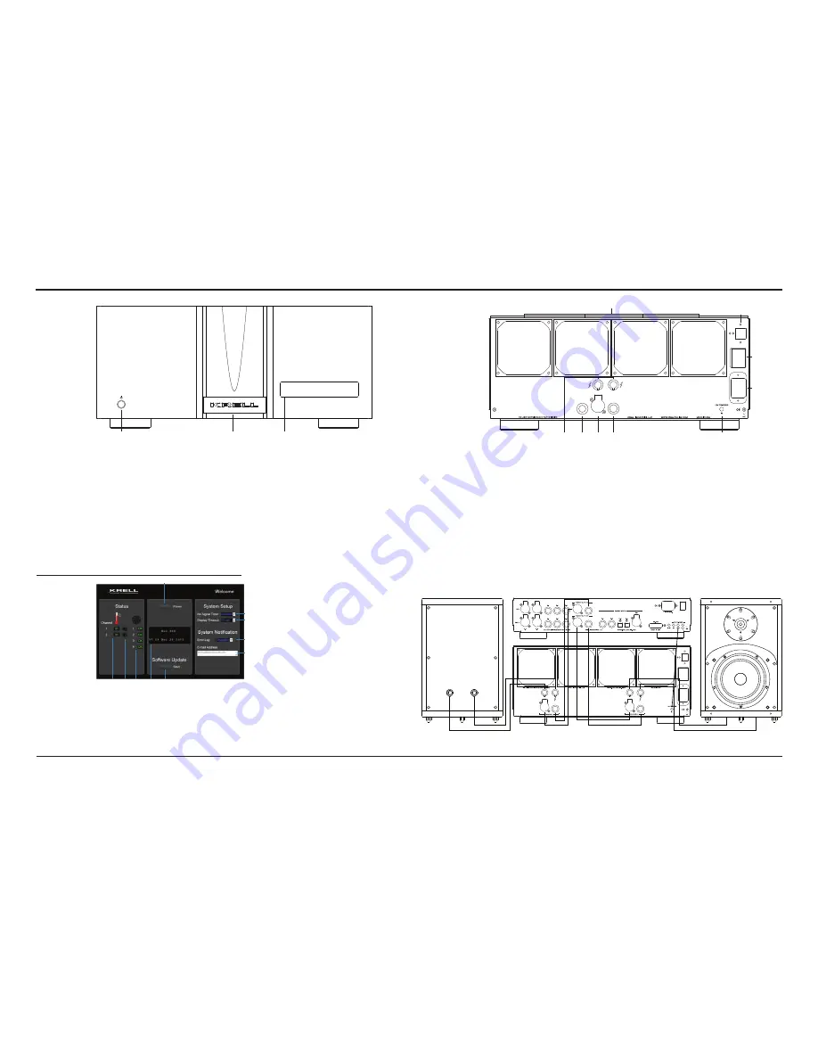
Figure 1 The iBias Front Panel
Figure 2
Network Control
Screen -
Duo 300 Shown
14
21
17
15
16
23
18
24
22
This product is manufactured in the United States of America. Krell
®
is a registered trademark of Krell Industries, LLC., and is restricted for
use by Krell Industries, LLC. its subsidiaries, and authorized agents. Krell Current Mode™ and CAST™ is a trademark of Krell Industries, LLC.
All other trademarks and trade names are registered to their respective companies.
© 2014 by Krell Industries, LLC., All rights reserved
Front Panel
Back Panel
1 Power Button
Use this button to switch
the iBias amplifier
between stand-by and
operational modes.
2 Power Indicator
The stand-by indicator
illuminates red when
the iBias amplifier
is plugged into a
standard AC wall
receptacle and the rear
panel power breaker
switch is in the up
position, indicating that
the amplifier is in the
stand-by mode and
ready to be switched
to the operational
mode. The indicator
illuminates blue when
the iBias amplifier is in
operational mode.
3 Front Panel Display
The front panel display
shows the model
number, firmware
version, serial number,
and IP address. Fault
conditions are also
displayed in the front
panel display.
After connecting the iBias
amplifier to a network via the
RJ 45 connector (18), enter
the amplifier's IP address into
the address bar of network
device on the same network.
The following additional
features are now available.
1 Temperature Monitoring
The iBias amplifiers monitor
the temperature of each
channel and adjust fan
speed to maintain proper
cooling. Temperatures listed
in green, yellow, and red,
indicating cool, warm, and
hot operating temperatures.
2 Channel Muting
Press the speaker icon
to mute and unmute an
individual channel
3 Fan Operation Status
Fan speed is monitored
and is indicated by a
green OK for proper
operation and a red E
for an error.
4 Display Window
Indicates amplifier stauts
and any fault conditions.
5 Software Update
Press this button to
initiate software update
6 Error Log
Set to Enabled to have
fault conditions sent to
the email addresses
listed in the E-mail
address window (7).
Network
Control
Figure 4 Connection Diagram
1
2
3
4
5
10
9
8
6
7
Figure 3 The iBias Back Panel - Solo 575 shown
7 E-mail Address window
Up to 3 email addresses
can entered to receive
fault condition emails.
8 Display Timeout
Set the time for how long
the front panel display
remains illuminated. The
Disabled option keeps
the display illuminated
indefintely.
9 No Signal Timer
Set the time for how long
the amplifier remains in
operational mode without
receiving an input signal.
The Disabled option
keeps the amplifier
in operational mode
indefintely.
Note
The network must have
internet access for features
5 and 6 to function.
14 Loudspeaker Outputs
The iBias amplifier is
equipped with standard
binding posts for each
amplifier channel.
15 Balanced Analog Inputs
The iBias amplifiers
are equipped with one
balanced input per channel
via XLR connector.
16 Single-Ended Analog
Inputs
The iBias amplifiers are
equipped with one single-
ended input per channel
via RCA connector.
17 CAST Inputs Solo 375
and Solo 575 only
The iBias mono amplifiers
are equipped with one
CAST input via a LEMO
connector and is for use
with a CAST equipped
preamplifier or surround
processor.
18 Ethernet Connection
The RJ45 connector is
used to connect an iBias
amplifier to a network.
Once the amplifier is
connected to a network
router with Internet access,
the amplifier’s advanced
protection systems are
now viewable on an
Internet-connected device.
Excessive current, output
DC, fan speeds, short
circuit, and overheating are
all monitored in real time.
If an issue occurs, the fault
is displayed on the front
panel and reported on
the web server interface.
Emails will automatically
be sent to as many as
three email addresses to
notify Krell, the end user
and/or the dealer of the
condition.
21 12 VDC In (12 V trigger)
The 12 V Trigger input
allows you to place the
iBias amplifier into the
stand-by or operational
mode from other
components.
22 IEC Connector
The connector is for use
with the provided IEC
standard 20 amp power
cord. This connector
and power cord must
remain unobstructed for
easy removal in case of
emergency.
23 Cooling Fans
iBias amplifiers come
equipped with up to four
fans. Please keep the
fan openings clear of
any obstructions to allow
proper air flow.
24 AC Power Breaker
Switch
Use this switch to change
the iBias amplifier from off
to the stand-by mode.
Note
Use only one type of connection: Single-ended, balanced, or CAST between Preamplifier and Amplifier


