background image

KRAMER:  SIMPLE CREATIVE TECHNOLOGY


Capturing the EDID 


10 

4.  Connect the 12V DC power adapter to the power terminal block (see  

Figure 2

on the 

WP-121

 and connect the adapter to the mains electricity.  

5.  Press the EDID capture button (see 

Figure 9

).  

The EDID status LED flashes slowly several times. The new EDID is 

captured when the LED stops flashing and lights solid. 

6.  Unplug the power adapter from the mains and disconnect it from the 

WP-121

7.  Replace the faceplate and secure the four screws removed in Step 1. 

6.2 Setting a Preconfigured EDID 

To set a preconfigured EDID: 

1.  Using a Philips screwdriver, remove the four screws holding the front panel to 

the rear PCB assembly.  

2.  Using a small screwdriver, turn the rotary switch (see 

Figure 9

) to the 

required position as defined in 

Table 6

. 

3.  Connect the 12V DC power adapter to the power terminal block (see  

Figure 2

) on the 

WP-121

 and connect the adapter to the mains electricity. 

4.  Press the EDID CAPTURE button (see 

Figure 9

)

The EDID status LED flashes rapidly several times. The new EDID is 

captured when the LED stops flashing and lights solid. 

5.  Unplug the power adapter from the mains and disconnect it from the 

WP-121

6.  Replace the faceplate and secure the four screws removed in Step 1. 

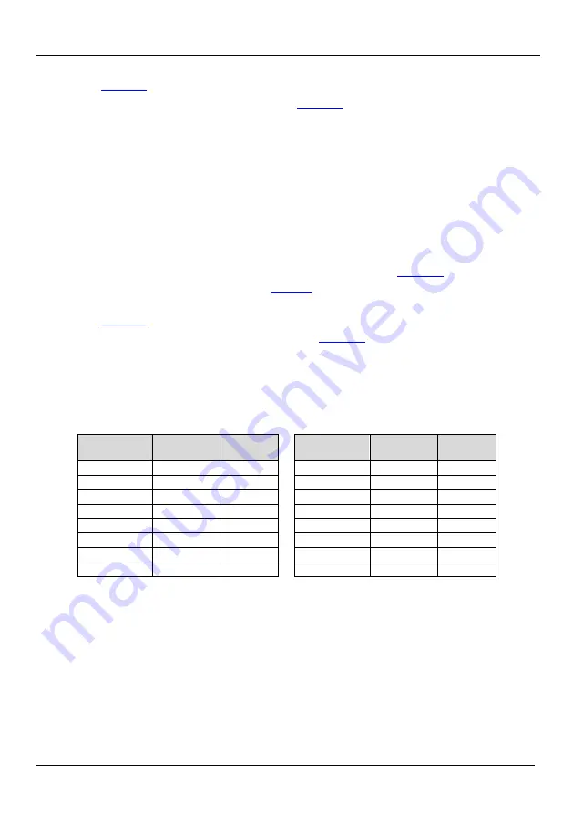
Table 6: Rotary Switch EDID Resolution Settings  

Rotary Switch 

Position 

Resolution 

Refresh 

Rate 


Rotary Switch 

Position 

Resolution 

Refresh 

Rate 

0 (Default) 

1024x768 

60Hz 


1440x900 

60Hz 

800x600 

60Hz 


1440x1050 

60Hz 

1024x768 

60Hz 


1600x1200 

60Hz 

1152x864 

75Hz 


1680x1050 

60Hz 

1280x720 

60Hz 


1920x1080 

60Hz 

1280x800 

60Hz 


1920x1200 

60Hz 

1024x1024 

60Hz 


For future use   

1360x768 

60Hz 


For future use   


Summary of Contents for WP-121

Page 1: ...Kramer Electronics Ltd USER MANUAL Model WP 121 XGA Unbalanced Stereo Audio Line Transmitter ...

Page 2: ...ctor 8 6 Capturing the EDID 9 6 1 Capturing the EDID from a Display Device 9 6 2 Setting a Preconfigured EDID 10 7 Technical Specifications 11 Figures Figure 1 WP 121 Front Panel 4 Figure 2 WP 121 Rear Panel 4 Figure 3 WP 121 80 86mm Front Panel 5 Figure 4 WP 121 80 86mm Rear Panel 5 Figure 5 Installing and Connecting the WP 121 6 Figure 6 WP 121 Grounding Components 7 Figure 7 TP Connector 8 Figu...

Page 3: ...tems WP 121 XGA Unbalanced Stereo Audio Line Transmitter A 12V DC power supply This user manual2 Note All references to WP 121 in this manual refer to the US version 69mm as well as to the WP 121 80mm and WP 121 86mm European versions 2 Getting Started We recommend that you Unpack the equipment carefully and save the original box and packaging materials for possible future shipment Review the cont...

Page 4: ...ate power supplies should be connected to the transmitter and to the receiver simultaneously 3 2 Shielded Twisted Pair Unshielded Twisted Pair We recommend that you use Shielded Twisted Pair STP cable There are different levels of STP cable available and we advise you to use the best quality STP cable that you can afford Our non skew free cable Kramer BC STP is intended for analog signals where sk...

Page 5: ...he output The WP 121 is supplied with a default EDID but it can also store and recall EDID data in non volatile memory allowing convenient and reliable connection to the source 3 4 Recommendations for Achieving the Best Performance Achieving the best performance means Utilizing only good quality connection cables thus avoiding interference deterioration in signal quality due to poor matching and e...

Page 6: ...ures Feature Function 1 AUDIO IN 3 5mm Mini Jack Connect to an unbalanced stereo audio source 2 PC IN XGA 15 Pin HD F Connector Connect to the XGA source 3 ON LED Lights red when receiving power lights green when receiving a signal from a video source Feature Function 4 12V PIN Power Removable Terminal Block Connect to the positive of the power adapter GND PIN Connect to the negative of the power ...

Page 7: ...Defining the WP 121 XGA Unbalanced Stereo Audio Line Transmitter 5 Figure 3 WP 121 80 86mm Front Panel Figure 4 WP 121 80 86mm Rear Panel ...

Page 8: ...put of the WP 121 to the pre installed STP wiring in the wall box opening that connects to the TP receiver or RJ 45 line output of the WP 121 to the pre installed STP wiring in the wall box opening that connects to the TP receiver 2 Recommended ground the wall plate see Section 5 3 3 Connect the 12V DC power supply to the power terminal block1 4 Insert the WP 121 into the wall box opening and secu...

Page 9: ...ing Screw Descriptions Item 1 M3x6 Screw 2 M3 Toothed lock washers 3 M3 Ring tongue terminal Figure 6 WP 121 Grounding Components The grounding screw is used to earth the chassis of the unit to the ground of the building thus preventing static electricity from interfering with the product s performance To connect the grounding to the WP 121 as illustrated in Figure 6 1 Crimp the ring tongue termin...

Page 10: ... White 6 Orange 6 Green 7 Brown White 7 Brown White 8 Brown 8 Brown Pair 1 4 and 5 Pair 1 4 and 5 Pair 2 3 and 6 Pair 2 1 and 2 Pair 3 1 and 2 Pair 3 3 and 6 Pair 4 7 and 8 Pair 4 7 and 8 5 4 2 Wiring the 9 Pin Terminal Block Line Output Connector The 9 pin terminal block is a plug in connector for attaching the STP cable Follow the colors of the color coded sticker on these terminals for proper c...

Page 11: ...DID Status LED Flashes slowly when capturing a valid display EDID Lights solid when EDID has been successfully captured Flashes rapidly when setting a preconfigured EDID 6 1 Capturing the EDID from a Display Device To capture the EDID from a display device 1 Using a Philips screwdriver remove the four screws holding the faceplate to the PCB assembly 2 Using a short cable1 3 Ensure that the rotary ...

Page 12: ...see Figure 9 to the required position as defined in Table 6 3 Connect the 12V DC power adapter to the power terminal block see Figure 2 on the WP 121 and connect the adapter to the mains electricity 4 Press the EDID CAPTURE button see Figure 9 The EDID status LED flashes rapidly several times The new EDID is captured when the LED stops flashing and lights solid 5 Unplug the power adapter from the ...

Page 13: ...EL Video 2Vpp Audio 2 8Vpp RESOLUTION Up to UXGA 1080p AUDIO BANDWIDTH 18KHz DIFF GAIN 1 8 DIFF PHASE 0 3 Deg K FACTOR 0 05 S N RATIO Video 60dB 5MHz Audio 71dB 1KHz COUPLING Video AC Audio AC AUDIO THD NOISE 0 07 AUDIO 2nd HARMONIC 0 001 POWER SOURCE 12V DC 340mA feeding a TP 112 or TP 122 od receiver OPERATING TEMPERATURE 0 to 55 C 32 to 131 F STORAGE TEMPERATURE 45 to 72 C 49 to 162 F HUMIDITY ...

Page 14: ...ter lightning orotheractsofnature ii Product modification orfailureto followinstructions supplied with theproduct iii Repairorattemptedrepairby anyonenot authorized byKramer iv Anyshipment oftheproduct claims must bepresentedtothe carrier v Removalorinstallationoftheproduct vi Anyothercause whichdoes not relateto aproduct defect vii Cartons equipment enclosures cables or accessoriesusedinconjuncti...

Page 15: ... REV 3 For the latest information on our products and a list of Kramer distributors visit www kramerelectronics com where updates to this user manual may be found We welcome your questions comments and feedback Caution Safety Warning Disconnect the unit from the power supply before opening servicing ...

Reviews: