P/N: 2900-301487 Rev 1
www.kramerAV.com
USER MANUAL
MODEL:
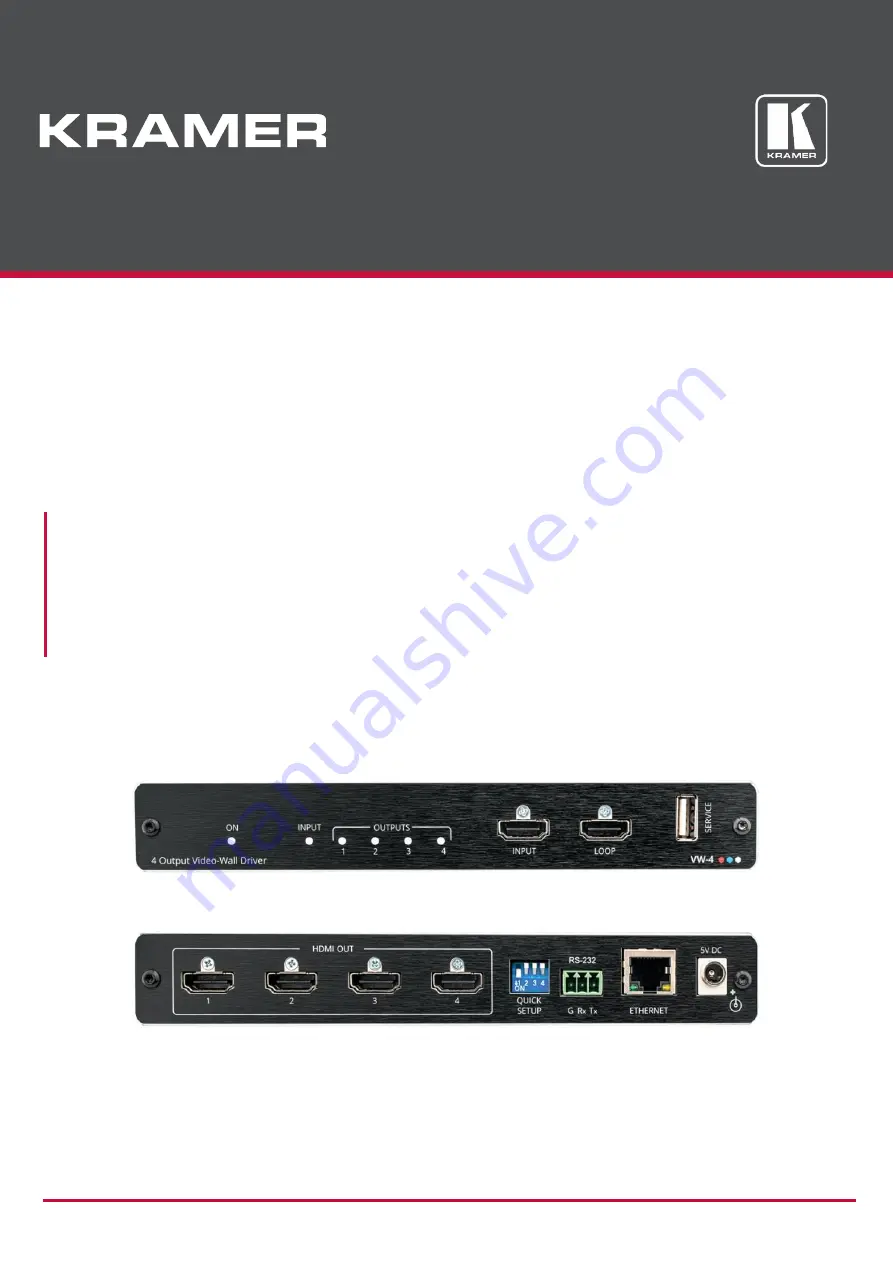
VW-4 4 Output Video-Wall Driver
Page 1: ...P N 2900 301487 Rev 1 www kramerAV com USER MANUAL MODEL VW 4 4 Output Video Wall Driver...
Page 2: ...ing VW 4 6 Connecting to VW 4 via RS 232 7 Connecting via Ethernet 7 Configuring VW 4 10 Configuring SETUP DIP Switches 10 Using the VW 4 App 11 Adjusting the Video Wall Image 24 Upgrading Firmware 25...
Page 3: ...er high performance high resolution cables to avoid interference deterioration in signal quality due to poor matching and elevated noise levels often associated with low quality cables Do not secure t...
Page 4: ...DIP switches VW 4 provides exceptional quality and user friendly operation Exceptional Quality Scalable Video walls Create and manage a video wall of up to 4 displays or by adding devices create vide...
Page 5: ...gnage Stock market displays Building lobbies Corporate offices In store retail promotion Convention and trade shows Controlling your VW 4 Control your VW 4 via DIP switch settings for basic video wall...
Page 6: ...perform firmware upgrade OUT HDMI Connectors 1 to 4 Connect to up to 4 HDMI acceptors that make up the video wall configuration The appropriate segments of the zoomed picture are output on these conn...
Page 7: ...ow is compatible for the device Avoid uneven mechanical loading Appropriate consideration of equipment nameplate ratings should be used for avoiding overloading of the circuits Reliable earthing of ra...
Page 8: ...re connecting it to your VW 4 After connecting your VW 4 connect its power and then switch on the power to each device Figure 2 Connecting to the VW 4 To connect VW 4 as illustrated in the example in...
Page 9: ...ither of the following methods Directly to the PC using a crossover cable see Connecting Ethernet Port Directly to PC on page 7 Via a network hub switch or router using a straight through cable see Co...
Page 10: ...ed network adapter appears as shown in Figure 3 Figure 3 Local Area Connection Properties Window 4 Highlight either Internet Protocol Version 6 TCP IPv6 or Internet Protocol Version 4 TCP IPv4 dependi...
Page 11: ...in the range 192 168 1 1 to 192 168 1 255 excluding 192 168 1 39 that is provided by your IT department Figure 6 Internet Protocol Properties Window 7 Click OK 8 Click Close Connecting Ethernet Port v...
Page 12: ...vices This can be very useful for quickly testing video wall functionality when setting up the system When the video wall size is configured using the DIP switches you cannot set it via the configurat...
Page 13: ...app to configure a video wall of up to 8x8 consisting of one or more VW 4 devices Download app from www kramerav com product VW 4 Tab_Resources VW 4 app enables performing the following actions Connec...
Page 14: ...the app Set each device with a unique IP address You can do this by connecting a device to the App and changing its IP address see Updating Network Settings on page 14 To Connect the video wall VW 4...
Page 15: ...ing a list of all the connected VW 4 devices and the available RS 232 ports on your PC Figure 8 Connection Window 4 Select a connected device under All Units and click The selected device moves to the...
Page 16: ...igure Caption 7 Click OK The app Status line indicates the number of devices selected and connected Video wall devices are connected Updating Network Settings Change the IP address and other Network s...
Page 17: ...or DHCP 5 Change Network settings as required 6 Click Save and then Reboot Network settings are updated Configuring Device Settings Once the devices are connected you can configure each of the video w...
Page 18: ...ected 0 is the first 1 the second and so on You can change that order to match your video wall configuration To change the ID of a device 1 Select the Settings tab 2 Place cursor next to the ID Figure...
Page 19: ...stick should only include this file 2 Select the Settings tab and then click System tab Figure 14 System Tab 3 Click Update The following message appears Figure 15 Firmware Update Message 4 Connect t...
Page 20: ...You can change Network settings via the Connection window see Updating Network Settings on page 14 To view Network settings 1 Select the Settings tab and then click Network tab 2 View the device Netwo...
Page 21: ...stick as a single file and connected to the SERVICE USB connector Select an EDID from the EDID dropdown box and then click Save You can copy the EDID from the display on one of the outputs Out 1 4 se...
Page 22: ...ys on Click Info to show information for a few seconds only after a change is made 3 Click next to Audio Mute to mute or unmute audio output 4 Select Auto sync off Disabled Slow or Fast from the drop...
Page 23: ...in one go Once the layout is set you can disconnect the devices from the Network If you are able to connect only one device at a time you need to set the layout separately for each device The Layout...
Page 24: ...t the video wall size in one of the following ways Selecting Column and Row numbers for example 3 x 2 Figure 20 Layout Tab 3x2 Video wall Setting Clicking Quick Selection for common video wall configu...
Page 25: ...settings tab 1 is the ID number of the second VW 4 in the wall 0 192 168 1 42 as defined via settings tab 1 to 4 indicate the HDMI outputs Video wall layout is defined Setting Bezel Corrections Enter...
Page 26: ...aspect ratio of the image is not maintained on the video wall The image on the input spreads over the entire video wall therefore you need to adjust the input image so it fits the video wall correctly...
Page 27: ...Kramer Electronics Ltd VW 4 Upgrading Firmware 25 Upgrading Firmware Upgrade the firmware via the app see Updating the Firmware on page 17 using the VW 4 SERVICE USB port 6...
Page 28: ...ace Indicators I O detection On LED Controls DIP switches for basic setup Computer app for comprehensive setup via Ethernet or RS 232 USB Firmware upgrade Power Consumption 5V DC 2 9A Source 5V DC 4A...
Page 29: ...efined Display type RGB color Screen size 120 x 90 mm 5 9 in Power management Not supported Extension blocs 1 CEA CTA EXT DDC CI n a Color characteristics Default color space Non sRGB Display gamma 2...
Page 30: ...720p at 50Hz HDTV 16 9 1 1 1920 x 1080i at 50Hz HDTV 16 9 1 1 1920 x 1080p at 50Hz HDTV 16 9 1 1 1920 x 1080p at 50Hz HDTV 16 9 1 1 1920 x 1080p at 50Hz HDTV 16 9 1 1 1920 x 1080p at 50Hz HDTV 16 9 1...
Page 31: ...5 4B 00 81 C0 81 80 A9 C0 A9 40 D1 C0 71 4F D1 00 81 00 08 E8 00 30 F2 70 5A 80 B0 58 8A 00 A0 5A 00 00 00 1E 28 3C 80 A0 70 B0 23 40 30 20 36 00 A0 64 00 00 00 1A 00 00 00 FC 00 56 57 2D 34 0A 20 20...
Page 32: ...ix nn Command Parameter CR LF Command parameters Multiple parameters must be separated by a comma In addition multiple parameters can be grouped as a single parameter using brackets and Command chain...
Page 33: ...MAND CPEDID edid_io src_id edid_io dest_bitmap CR or CPEDID edid_io src_id edid_io dest_bitmap CR FEEDBACK nn CPEDID edid_io src_id edid_io dest_bitmap CR LF nn CPEDID edid_io src_id edid_io dest_bitm...
Page 34: ...input 3 Follow output Set the input HDCP MODE of the HDMI input to Off HDCP MOD 0 1 0 CR HDCP MOD Get HDCP mode Set HDCP working mode on the device input HDCP supported HDCP_ON default HDCP not suppo...
Page 35: ...hine_name String of up to 15 alpha numeric chars can include hyphen not at the beginning or end Set the DNS name of the device to room 442 NAME room 442 CR NAME Get machine DNS name The machine name i...
Page 36: ...s case the Network ID by default is 0 which is the Ethernet control port COMMAND NET MAC id CR FEEDBACK nn NET MAC id mac_address CR LF id Network ID the device network interface if there are more tha...
Page 37: ...SIGNAL 1 CR SN Get device serial number COMMAND SN CR FEEDBACK nn SN serial_num CR LF serial_num 14 decimal digits factory assigned Get the device serial number SN CR VERSION Get firmware version num...
Page 38: ...nough space for data firmware FPGA ERR_FS_NOT_ENOUGH_SPACE 11 Not enough space file system ERR_FS_FILE_NOT_EXISTS 12 File does not exist ERR_FS_FILE_CANT_CREATED 13 File can t be created ERR_FS_FILE_C...
Page 39: ...ized dealer from which it was purchased or any other party authorized to repair Kramer Electronics products this product must be insured during shipment with the insurance and shipping charges prepaid...
Page 40: ...nd a list of Kramer distributors visit our website where updates to this user manual may be found We welcome your questions comments and feedback The terms HDMI HDMI High Definition Multimedia Interfa...