


#
Feature
Function
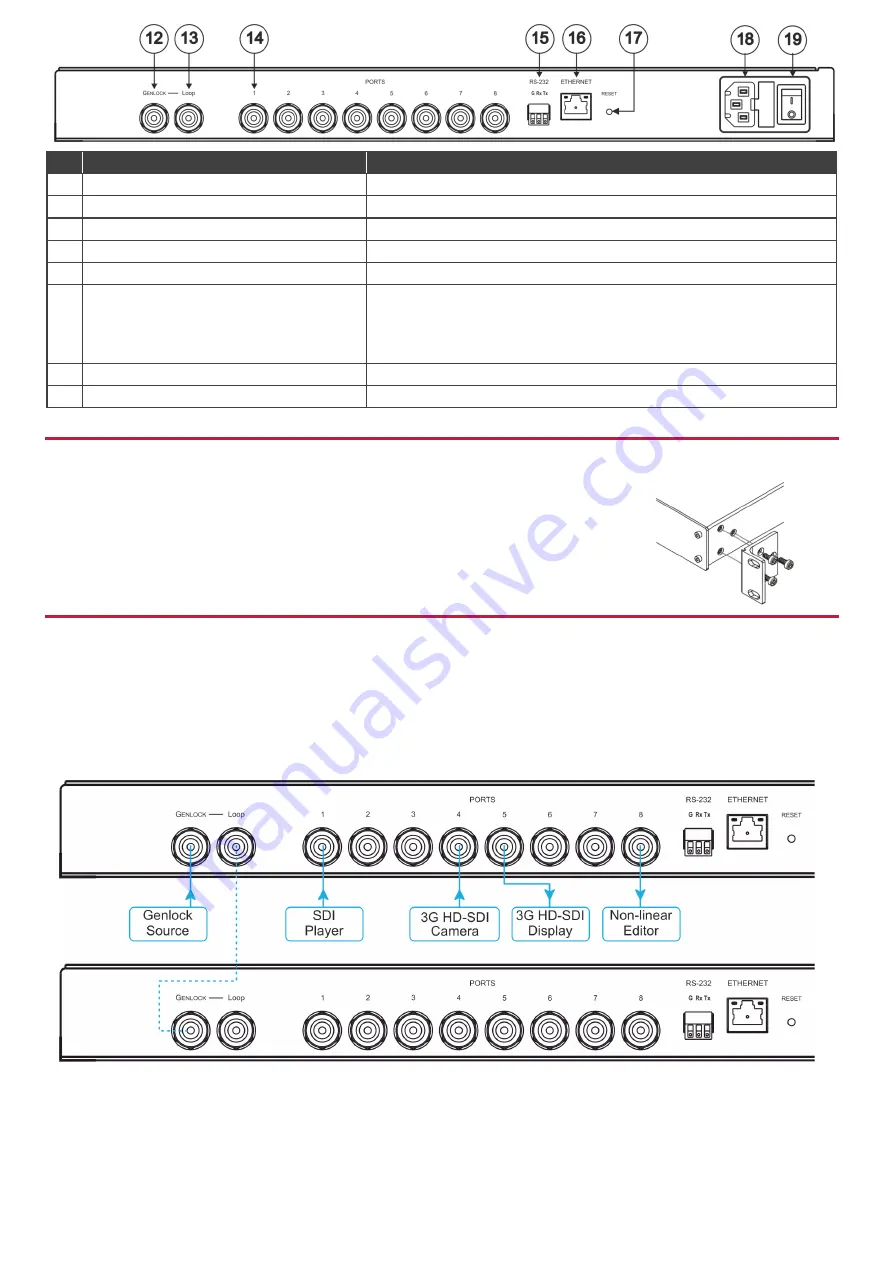
12
GENLOCK BNC Connector
Connect to the GENLOCK source.
13
LOOP BNC Connector
Connect to the GENLOCK connector of the next unit in the daisy chain.
14
PORTS BNC Connectors
Connect to sources and acceptors (8 in total, or 4 in total for dual mode).
15
RS-232 (G,Rx,Tx) Terminal Block Connector
Connect to a PC or remote controller.
16
ETHERNET RJ-45 Connector
Connect to a PC via LAN and also used for firmware upgrade.
17
RESET Button
Press briefly to restart the system.
Press for 10 seconds to reset IP settings to factory default values.
The device powers up and loads the factory default values:
IP address: 192.168.1.39; Mask: 255.255.255.0; Gateway 192.168.1.1.
18
Power Socket
AC connector enabling power supply to the
VS-8FDxl
.
19
Power Switch
Illuminated switch for turning the unit ON and OFF.
Step 3: Install the VS-8FDxl
To rack mount the machine attach both ear brackets to the machine (by removing the three screws
from each side of the machine and replacing those screws through the ear brackets) or place the
machine on a table.
Step 4: Connect the inputs and outputs
Each
VS-8FDxl
port can be defined as an input or an output, enabling flexible configurations such as 1x7 distribution amplifiers, 7x1
routers or any other possible input-output combination. By default, the
VS-8FDxl
is set to operate as a 4x4 router: PORT 1 to PORT
4 as the inputs, and PORT 5 to PORT 8 as the outputs.
Always switch OFF the power on each device before connecting it to your
VS-8FDxl
. For best results, we recommend that you
always use Kramer high-performance cables to connect AV equipment to the
VS-8FDxl
.
Optionally, daisy-chain the
VS-8FDxl
by looping the genlock source to the next machine.


