


Switch an input to an output via front panel buttons
Use the front panel buttons for the following switching modes:
Press
VIDEO
to switch the video signal of a selected input to the selected output.
Press
D-AUDIO
(HDMI embedded audio signal) to switch the digital audio signal of a selected input to the selected output.
Press
A-AUDIO
(analog signal on 3.5mm mini jack) to switch the analog audio signal of a selected input to the selected
output.
Press
VIDEO
+
D-AUDIO
simultaneously to switch the video and digital audio signals of a selected input to the selected
output.
Press
VIDEO
+
A-AUDIO
simultaneously to switch the video and analog audio signals of a selected input to the selected
output.
Press
MUTE/PATTERN
to switch the pattern signal of a selected input to the selected output.
Press
D-AUDIO
+
A-AUDIO
and then an input button to set that input source to ARC.
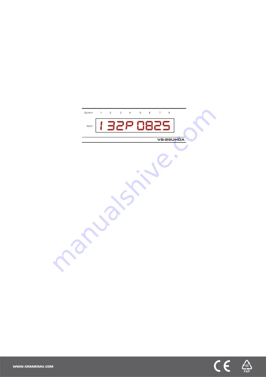
7-segment display example
When in Video mode, the 7-segment display shows the input-output status:
In this example: Input 1 is routed to output 1, input 3 is routed to output 2, input 2 is routed to outputs 3 and 7, a pattern is routed to
output 4, output 5 is set to mute, and so on.
Read the EDID via the front panel buttons
To read the EDID from the output:
1. Press
EDID
+
STO
.
The EDID and STO button LEDs light. The 7-segment display shows the current EDID status.
2. Press one or more input buttons or press
ALL
, the corresponding 7-segment LEDs flash.
3. Press an output button that is connected to a display. The 7-segment LEDs show the output number from which the EDID is
read.
4. Press
EDID
. Wait approx. 5 seconds. The EDID of the display is copied to the input port/s and the device exits EDID mode.
To read the default EDID:
1. Press
EDID
+
STO
.
The EDID and STO button LEDs light. The 7-segment display shows the current EDID status.
2. Press one or more input buttons or press
ALL
, the corresponding 7-segment LEDs flash.
3. Press
MUTE/PATTERN
. The 7-segment LED flashes
and shows “d”.
4. Press
EDID
. Wait approx. 5 seconds. The default EDID is copied to the input port/s and the device exits EDID mode.
Use the VS-88UHDA Web pages
Switching:
Set input and output parameters (HDCP support, switching speed, and so on), select switching modes, set test patterns,
perform switching operations, and so on.
Device Settings:
View device parameters (model, name, serial number, and so on), set network parameters, perform firmware
upgrade, and reset to factory defaults.
Password Settings:
Set password for Admin.
Timeout Settings:
Set the timeout per output when no signal is detected.
Auto Switch Settings:
Set switch mode (manual, last connected, or priority), select the ports included in the last connected mode;
set the priority order.
Step-in Settings:
Control Step-in devices that are connected to the inputs. Select a device (that is connected to a
VS-88UHDA
input), set the input signal type, and set the outputs to which the input signal is switched when the Step-in button is pressed (on the
Step-in device).
EDID Management:
Set the default EDID or read the EDID from an output or file to one or more of the inputs.


