

VP-8X8
Quick Start
P/N: 2 9 0 0 - 3 0 1 2 5 8 QS
Rev: 3
Scan for full manual
VP-8X8 Quick Start Guide
This guide helps you install and use your
VP-8X8
for the first time.
www.kramerav.com/downloads/VP-8X8
to download the latest user manual and check if firmware
upgrades are available.
Step 1: Check
what’s in the box
VP-8X8
Matrix Switcher
1 Set of rack ears
4 Rubber feet
Kramer
RC-IR3
Infrared Remote Control
Transmitter (with battery and user manual)
1 Power cord
1 Quick start guide
1 Null-modem adapter
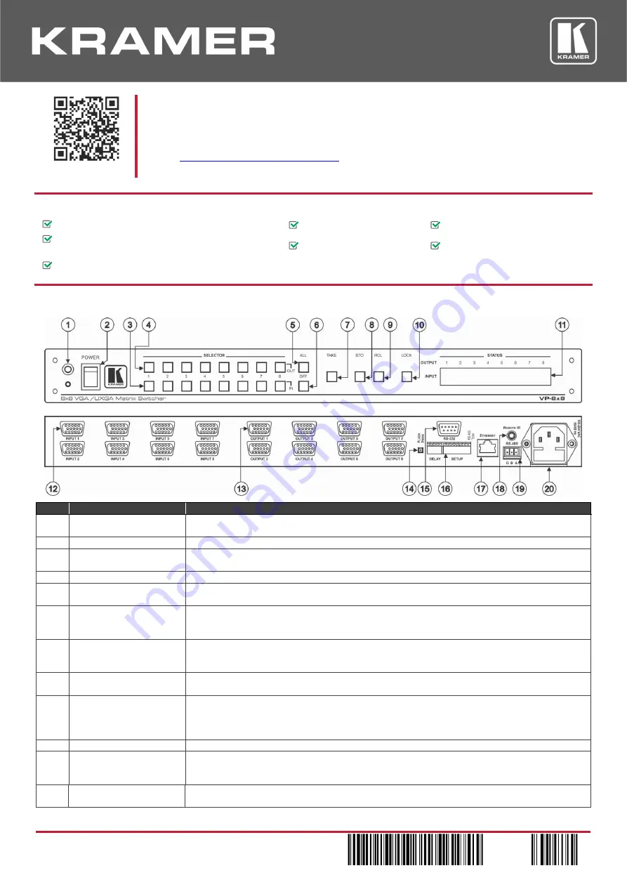
Step 2: Get to know your VP-8X8
#
Feature
Function
1
IR Receiver
The yellow LED is illuminated when receiving signals from the infrared remote control
transmitter
2
POWER
Switch
Illuminated switch for turning the unit ON or OFF
3
IN SELECTOR
Buttons
Select the input to switch to the output.
When a signal is detected, the input button illuminates in green
4
OUT SELECTOR
Buttons Select the output to which the input is switched
5
ALL
Button
Pressing ALL followed by an INPUT button, connects that input to all outputs
For example, press ALL and then Input button # 2 to connect input # 2 to all the outputs
6
OFF
Button
Press an
OUT
SELECTOR button and then an
OFF
button to disconnect that output from the
inputs.
Press the
ALL
button and then the
OFF
button to disconnect all the outputs
7
TAKE
Button
Pressing
TAKE
toggles the mode between the Confirm mode and the At Once mode (user
confirmation per action is unnecessary)
When in the Confirm mode, the TAKE button illuminates
8
STO
(Store) Button
Pressing
STO
followed by an input/output button stores the current setting
For example, press STO and then the Output button # 3 to store in Setup # 3
9
RCL
(
Recall
) Button
Pressing the
RCL
button and the corresponding
IN
/
OUT
button recalls a setup from the non-
volatile memory. The stored status flashes. Pressing a different
IN
/
OUT
button lets you view
another setup. After making your choice, pressing the
RCL
button again implements the new
status
10
LOCK
Button
Disengages the front panel switches
11
STATUS
7-segment
Display
Displays the selected input switched to the output (marked above each input)
Also displays the number of IN and OUT ports, the firmware version number, and the
MACHINE #.
12
15-pin HD
INPUT
Connectors
Connect to the video sources (from 1 to 8)


