background image

KRAMER:  SIMPLE CREATIVE TECHNOLOGY


Your VP-727A-BA Balanced Audio Switcher 


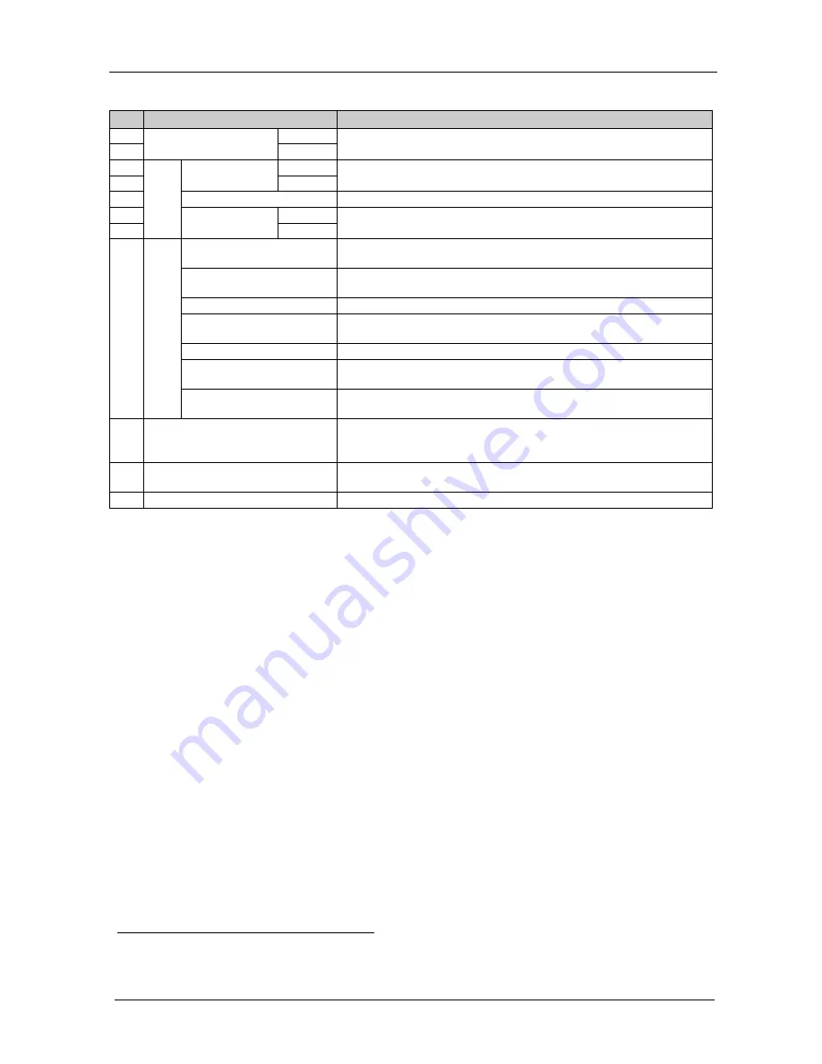
Table 2: VP-727A-BA Balanced Audio Switcher Rear Panel Features 

Feature 

Function 

18 

INPUT 

XLR F 

Connectors


RIGHT 

Connect to the balanced stereo audio source (from 1 to 8) 

19 

LEFT 

20 

OUTPUTS


PREVIEW 

XLR 

M Connectors


LEFT 

Connect to a balanced stereo audio preview acceptor 

21 

RIGHT 

22 

S/PDIF

 RCA Connector


Connect to a digital audio acceptor 

23 

PROGRAM 

XLR 

M Connectors


RIGHT 

Connect to a balanced stereo audio program acceptor 

24 

LEFT 

25 

SETUP DIPs

1

DIP 8 


Set to ON to operate the 

VP-727A-BA

 with the 

VP-727xl 

(as slave baud 

rate 38,400); else set to OFF 

DIP 7


Set to ON to operate the 

VP-727A-BA

 with the 

VP-727

 or the 

VP-727T


(as chain baud rate 115,200); else set to OFF 

DIP 6 

Set to ON for stand alone


(baud rate 9,600); else set to OFF 

DIP 5  

Set to ON for the fade to follow the transition effect; set to OFF for 

separate fade 

DIPs 3 and 4  

Set to OFF (default) 

DIP 2  

Set to ON for RS-485 Line Termination with 120

; set to OFF for no 

RS-485 Line Termination 

DIP 1 

Set to ON to upgrade to the latest Kramer firmware (see section  7); set 

to OFF for normal operation (the factory default) 

26 

RS-485 Port 

Connects to the Kramer 

VP-727T

 or the 

VP-727xl

 (see section  6.4) 

Pin G is for the Ground connection

2

27 

; pins B (-) and A (+) are for 

RS-485 

RS-232

 Connector 

9-pin D-sub connector connects to a PC or Remote Controller via a  

null-modem connection 

28 

Power Connector with Fuse 

AC connector enabling power supply to the unit 


1 By default, DIPs 1 to 7 are set to OFF and DIP 8 is set to ON 
2 The ground connection is sometimes connected to the shield of the RS-485 cable. However, usually the ground is not connected 

Summary of Contents for VP-727A-BA

Page 1: ...Kramer Electronics Ltd USER MANUAL Model VP 727A BA Balanced Audio Switcher...

Page 2: ...igure 1 VP 727A BA Balanced Audio Switcher 4 Figure 2 Connecting the VP 727A BA with a VP 727xl Machine 9 Figure 3 Connecting the PC 10 Figure 4 Connecting 2 VP 727A BA machines to the VP 727T via 2 V...

Page 3: ...er Power cord2 Null modem adapter This user manual 2 Getting Started We recommend that you Unpack the equipment carefully and save the original box and packaging materials for possible future shipment...

Page 4: ...KRAMER SIMPLE CREATIVE TECHNOLOGY Getting Started 2...

Page 5: ...r executing preview to program switching with transition effects An audio follow video button when operating in conjunction with the VP 727xl or the VP 727 Separate input and output level control Fade...

Page 6: ...KRAMER SIMPLE CREATIVE TECHNOLOGY Your VP 727A BA Balanced Audio Switcher 4 Figure 1 VP 727A BA Balanced Audio Switcher...

Page 7: ...Press to select2 which output PROGRAM or the PREVIEW to send to the headphones 12 AUDIO LEVEL 7 segment Display Displays the numerical value of the CONTROL feature4 13 Button Press to increase the le...

Page 8: ...set to OFF DIP 6 Set to ON for stand alone baud rate 9 600 else set to OFF DIP 5 Set to ON for the fade to follow the transition effect set to OFF for separate fade DIPs 3 and 4 Set to OFF default DI...

Page 9: ...to 45 C 41 to 113 F Operating humidity range 10 to 90 RHL non condensing Storage temperature range 20 to 70 C 4 to 158 F Storage humidity range 5 to 95 RHL non condensing CAUTION When installing in a...

Page 10: ...kers 3 Connect the RS 485 terminal block connector on the VP 727A BA to the AUDIO CONTROL terminal block connector of the Kramer VP 727xl 4 On the VP 727A BA set DIP 8 to ON5 5 Connect the RS 485 term...

Page 11: ...Configuring the VP 727A BA Balanced Audio Switcher 9 Figure 2 Connecting the VP 727A BA with a VP 727xl Machine...

Page 12: ...t on the VP 727A BA unit to the Null modem adapter and connect the Null modem adapter with a 9 wire flat cable to the RS 232 9 pin D sub port on your PC To connect a PC to a VP 727A BA unit without us...

Page 13: ...ed to the and the VP 727T VP 727xl see Figure 4 or the VP 727 see Figure 5 VP 727T via the VP 727xl or the VP 727 using the RS 485 ports The example in Figure 4 illustrates how to connect two VP 727A...

Page 14: ...ced Audio Switcher 12 The example in Figure 5 illustrates how to connect a VP 727A BA and a VP 727 machine to a VP 727T controller On the VP 727A BA set DIP 7 to ON The other dipswitches are set to OF...

Page 15: ...IN on the AUDIO CONTROL rear panel port of the VP 727xl unit Connect the B PIN on the RS 485 rear panel port of the VP 727A BA to the B PIN on the AUDIO CONTROL rear panel port of the VP 727xl unit If...

Page 16: ...MPLE CREATIVE TECHNOLOGY Configuring the VP 727A BA Balanced Audio Switcher 14 VP 727T Side Panel VP 727xl RS 485 PINOUT G B A _ VP 727A BA Figure 6 RS 485 Configuration between the VP 727A BA and the...

Page 17: ...RS 485 rear panel port of the VP 727A BA to the B PIN on the AUDIO CONTROL rear panel port of the VP 727 unit If shielded twisted pair cable is used the shield may be connected to the G Ground PIN on...

Page 18: ...SIMPLE CREATIVE TECHNOLOGY Configuring the VP 727A BA Balanced Audio Switcher 16 VP 727T Side Panel VP 727A BA VP 727 RS 485 PINOUT G B A _ Figure 7 RS 485 Configuration between the VP 727A BA and the...

Page 19: ...ile FLIP_VP727A BA zip to a folder for example C Program Files Kramer Flash 3 Create a shortcut on your desktop to the file FLIP EXE 7 2 Connecting the PC to the RS 232 Port Before installing the late...

Page 20: ...IP EXE The Splash screen appears as follows Figure 8 Splash Screen 2 After a few seconds the Splash screen is replaced by the Atmel Flip window Figure 9 Atmel Flip Window 3 Press the keyboard shortcut...

Page 21: ...gure 10 Device Selection Window 4 Click the button next to the name of the device and select from the list AT89C51RD2 AT89C51RD2 T89C51RD2 Figure 11 Selecting the Device Window 5 Click OK and select L...

Page 22: ...select the Communication RS232 command from the Settings menu or press the keys Alt SCR The RS232 window appears Change the COM port according to the configuration of your computer and select the 960...

Page 23: ...een 1 When the operation is completed all 4 check boxes will be colored green and the status bar message Memory Verify Pass appears 2 Figure 15 Atmel Flip Window Operation Completed 10 Close the Atmel...

Page 24: ...PUT LEVEL 4 5Vpp BANDWIDTH 3dB 22kHz S N RATIO 85dB CROSSTALK 1kHz all hostile Program 88dB Preview 92dB Balanced 88dB Phones Preview 82dB Phones Program 80dB CONTROLS Preview level 72dB to 62dB in an...

Page 25: ...81 81 See NOTE 1 RESET 00 80 80 81 INPUT 1 PROGRAM OUT 02 81 81 81 INPUT 2 PROGRAM OUT 02 82 81 81 INPUT 3 PROGRAM OUT 02 83 81 81 Select INPUT 4 PROGRAM OUT 02 84 81 81 Input INPUT 5 PROGRAM OUT 02 8...

Page 26: ...VEL 16 88 80 Value 81 READ PROGRAM INPUT 1 LEVEL 19 81 80 81 See NOTE 3 READ PROGRAM INPUT 2 LEVEL 19 82 80 81 READ PROGRAM INPUT 3 LEVEL 19 83 80 81 READ PROGRAM INPUT 4 LEVEL 19 84 80 81 READ PROGRA...

Page 27: ...16 A1 80 Value 81 See NOTE 1 PREVIEW OUTPUT LEVEL 16 A2 80 Value 81 HEADPHONE OUTPUT LEVEL 16 A3 80 Value 81 READ PROGRAM OUTPUT LEVEL 19 A1 80 81 See NOTE 3 READ PREVIEW OUTPUT LEVEL 19 A2 80 81 REA...

Page 28: ...PUT 8 DELAY 19 C8 80 81 AFV 08 80 80 81 See NOTE 1 BREAKAWAY 08 80 81 81 READ AFV BREAKAWAY STATUS 0B 80 80 81 See NOTE 3 FADE ON 20 80 81 81 See NOTE 1 FADE OFF 20 80 80 81 See NOTE 1 READ FADE STATU...

Page 29: ...81 NOTE 2 In the case of an error the reply code will be 1st byte 0x50 2nd 3rd and 4th byte don t care NOTE 3 The reply to these READ commands is 1st byte 0x40 1st byte sent 2nd byte Same as the data...

Page 30: ...version as 1st byte 0x7d 2nd byte 0x80 the version number prior to decimal point 3rd byte 0x80 the version number following the decimal point 4th byte 0x81 For example for version 3 5 the reply would...

Page 31: ...fnature ii Product modification orfailureto followinstructions supplied with theproduct iii Repairorattemptedrepairby anyonenot authorized byKramer iv Anyshipment oftheproduct claims must bepresentedt...

Page 32: ...or the latest information on our products and a list of Kramer distributors visit our Web site www kramerelectronics com where updates to this user manual may be found We welcome your questions commen...

Reviews: