


KRAMER: SIMPLE CREATIVE TECHNOLOGY
Your RGBH / Balanced Audio Matrix Switcher
10
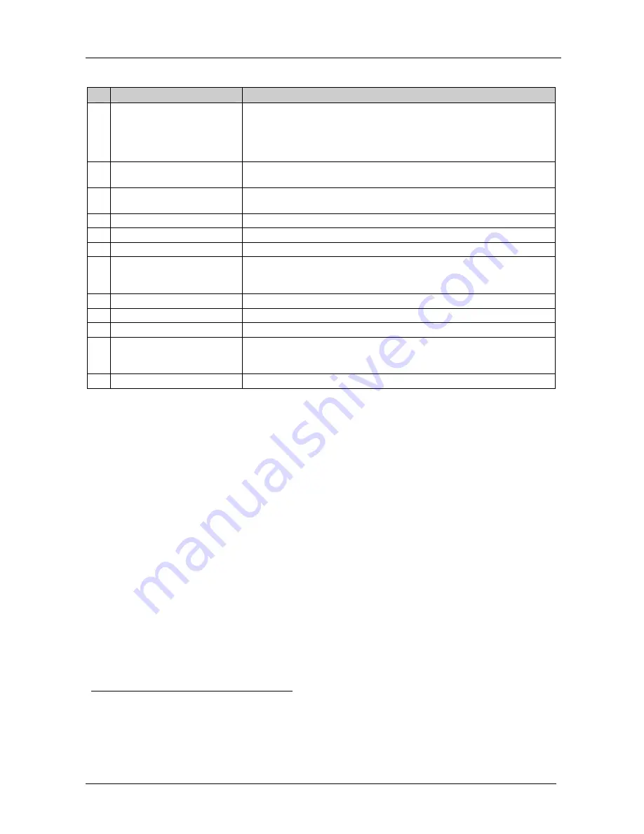
Table 2: The RGBH / Balanced Audio Matrix Switcher Rear Panel
Features
#
Feature
Function
14
TERM: 75 /TTL
Buttons
When both buttons are released, the upper input channels are used for
TTL level H & V sync signals (RGBHV operation);
When both buttons are pushed in, the input channels become analog video
channels, just as the lower RGB channels, and the machine can be used
for 5 identical video channels
15
AUDIO INPUTS
1
Terminal
Block Connectors
Connect to the balanced stereo audio sources
16
AUDIO OUTPUTS
1
Terminal
Block Connectors
Connect to the balanced stereo audio acceptors
17
RS-485
Port
Pin G is for the Ground connection
2
; pins B (-) and A (+) are for RS-485
18 Ethernet Connector
Connects to the PC or other Serial Controller through computer networking
19 Power Connector with Fuse
AC connector, enabling power supply to the unit
20 Dipswitches
Dipswitches for setup of the unit (1, 2 and 3 are for setting the machine
number; 4 is for RS-485 bus termination; 5 is for Reply; 8 is for RS-485 PC
communication)
21
RS-232
DB 9F Port
Connects to the PC or the remote controller
22
OUT
BNC Connectors
Connect to the video acceptors
23
INPUTS
BNC Connectors
Connect to the video sources
24
EXT./IN 1
Button
When pushed in selects an external sync from the external source; when
released selects the internal sync (inputted via the video input #1
connectors)
25
EXT. SYNC
BNC Connector
Connects to the external sync source
1
VP-88ETH has 8 inputs and 8 outputs; VP-84ETH has 8 inputs and 4 outputs; VP-82ETH has 8 inputs and 2 outputs;
VP-66ETH has 6 inputs and 6 outputs; VP-64ETH has 6 inputs and 4 outputs
2
The ground connection is sometimes connected to the shield of the RS-485 cable. In most applications, the ground is not
connected


