


Your UXGA / Audio Matrix Switcher
5
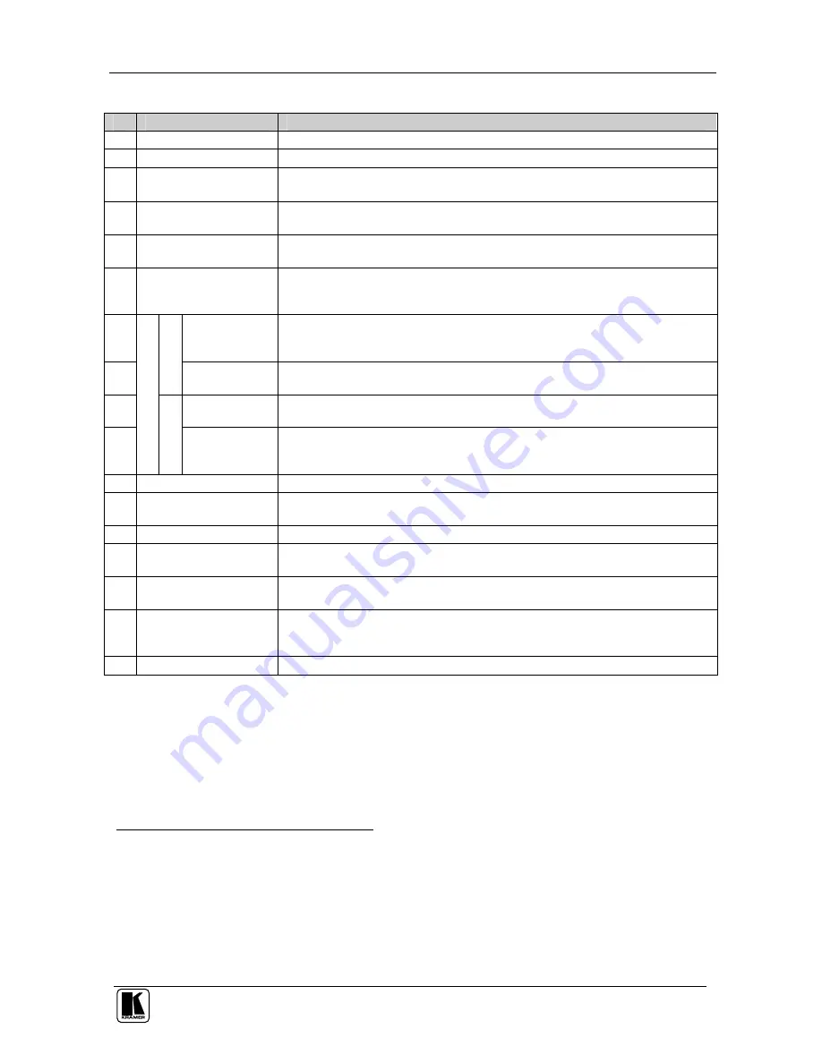
Table 1: Front Panel VP-4x4xl 4x4 UXGA / Audio Matrix Switcher Features
#
Feature
Function
1
IR (Infra-Red) Receiver
Signals from the remote control transmitter illuminate the LED
2
POWER
Switch
Illuminated switch for turning the unit ON or OFF
3
SELECTOR IN
Buttons Select the input to switch to the output
1
When a signal is detected, the input button illuminates in green
4
SELECTOR OUT
Buttons
Select the output to which the input is switched
5
ALL
Button
Pressing ALL before pressing an input button connects that input to all
outputs
2
6
OFF
Button
Pressing OFF after pressing an output button disconnects that output from the
inputs. To disconnect all the outputs, press the ALL button and then the OFF
button
7
STATUS
IN
7-segment
Display
Displays the selected video
input switched to the output (marked above each
input). Also displays the number of IN and OUT ports
3
8
V
ID
E
O
STATUS OUT
Labels
Identifies a cross point between each video output to which the video input
displayed below it is connected
9
STATUS OUT
Labels
Identifies a cross point between each audio output to which the audio input
displayed below it is connected
10
S
TA
TU
S
A
U
D
IO
STATUS IN
7-segment
Display
Displays the selected audio input switched to the output (marked above each
input). Also displays the firmware version number and the MACHINE #
3
11
VID
Button
When illuminated
4
actions relate to video
12
AFV
Button
When illuminated, the audio channels follow the video channels. The button is
illuminated when the AFV mode is selected
13
AUD
Button
When illuminated
5
actions relate to audio
14
STO
Button
Pressing STO (STORE) followed by an output button stores the current
setting
6
15
RCL
Button
Pressing
RCL
(RECALL) followed by an output button displays a stored
setup. Pressing the RCL button again implements the new status
16
TAKE
Button
Pressing TAKE toggles the mode between the CONFIRM mode
7
and the AT
ONCE mode (user confirmation per action is unnecessary). When in
CONFIRM mode, actions are confirmed by pressing the TAKE key
17
LOCK
Button
Disengages the front panel switches
1 The SELECTOR IN
and OUT buttons also store/recall the input/output configurations (see section 7.5)
2 For example, press ALL and then Input button # 2 to connect input # 2 to all the outputs
3 Refer to section 7.1
4 The VID button is illuminated when in breakaway mode and actions relate to video
5 The AUD button is illuminated when in breakaway mode and actions relate to audio
6 For example, press STO and then the Output button # 3 to store in Setup # 3
7 When in the CONFIRM mode, the TAKE button illuminates


