background image


14 

VA-8xl - Controlling the VA-8xl 


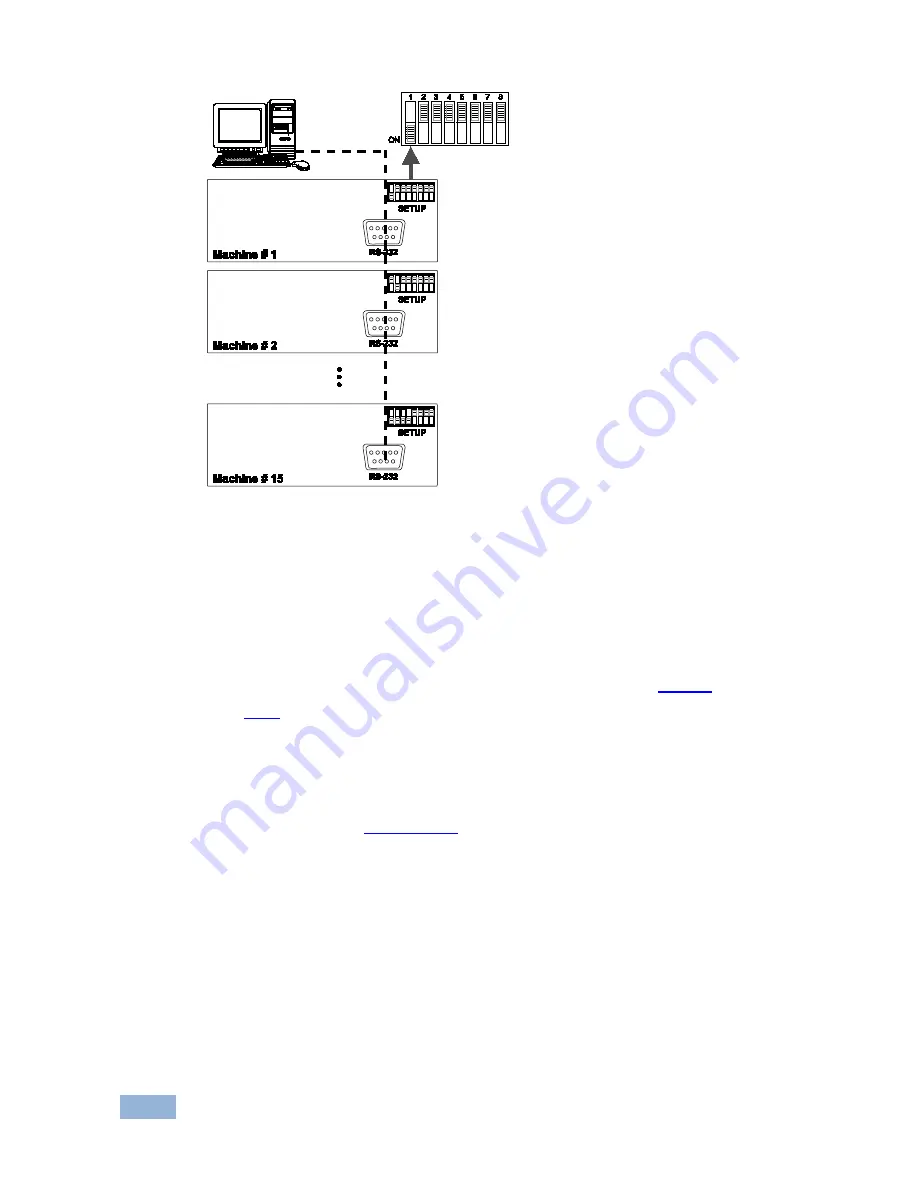
Figure 10: Configuring up to 15 VA-8xl Units 

6.3.1 

Connecting a Control Interface on a Set of Units 

To connect the control interface on a set of units, do one of the following: 


Connect the RS-232 port on the first 

VA-8xl

 unit to a PC or other 

controller, and then connect the RS-232 port on each of the 

VA-8xl

 units, using the specially prepared RS-232 cable (see 

Section 

 6.3.2

or


Connect a PC or other controller to the “RS-232 in” 9-pin D-sub (F) 
port on a Kramer Tools 

VP-43xl

 Interface Converter

 and connect the 

RS-485 port on the 

VP-43xl

 to the RS-485 ports on each of the 

VA-8xl

 units (see 

Section  6.3.3

6.3.2 

Preparing the RS-232 Port on a Set of Units 

To connect a PC to a set of 

VA-8xl

 units do the following: 

1.  Prepare the RS-232 9-pin D-sub (F) connector (A), by connecting PIN 4 to 

PIN 6 and connecting PINS 8, 7, and 1 together. 

Summary of Contents for VA-8XL

Page 1: ...KRAMER ELECTRONICS LTD USER MANUAL MODEL VA 8xl 8 Channel Balanced Stereo Audio Amplifier P N 2900 300151 Rev 1...

Page 2: ......

Page 3: ...fication Gain Control 28 10 3 Channel Number Codes 28 Figures Figure 1 VA 8xl 8 Channel Balanced Stereo Audio Amplifier Front Panel 4 Figure 2 VA 8xl 8 Channel Balanced Stereo Audio Amplifier Rear Pan...

Page 4: ...are clearly defined by function GROUP 1 Distribution Amplifiers GROUP 2 Switchers and Matrix Switchers GROUP 3 Control Systems GROUP 4 Format Standards Converters GROUP 5 Range Extenders and Repeater...

Page 5: ...com to check for up to date user manuals application programs and to check if firmware upgrades are available where appropriate 2 1 Achieving the Best Performance To achieve the best performance Use...

Page 6: ...ns 8 independent channels Control of the amplifier gain of the left and right channels together or separately via the front panel buttons or remotely via RS 232 or RS 485 Daisy chaining of up to 15 ma...

Page 7: ...Buttons DOWN a Decreases the volume in increments of 0 5dB from 95dB to 31dB gain b Stores the current setting in the non volatile memory 4 LEFT Selects deselects the left channel 5 UP a Increases the...

Page 8: ...s from 1 to 8 10 OUT Terminal Block Connectors Connect to audio acceptors from 1 to 8 11 RS 485 Detachable Terminal Block Port Pin 1 is for Ground Pin 2 is for Pin 3 is for 12 RS 232 9 pin D sub Port...

Page 9: ...lanced stereo audio sources for example a tape deck to INPUT CHANNEL 1 8 via terminal block connectors You do not have to connect all channels 2 Using the appropriate wiring shown in the figures below...

Page 10: ...VA 8xl Connecting the VA 8xl 7 Figure 6 Connecting the VA 8xl 8 Channel Balanced Stereo Audio Amplifier...

Page 11: ...for observation only You can control the amplifier gain of the left and right channels via the front panel buttons or remotely via RS 232 or RS 485 You can increase or decrease the gain in increments...

Page 12: ...the selected channel that appears in the dimmed LED displays and each setting includes all 8 channels To store a setting via the front panel buttons 1 When the LED displays are dimmed press the DOWN...

Page 13: ...and the number of that CHANNEL SELECTOR button appears in the RIGHT LED display 3 Press the same CHANNEL SELECTOR button again The memory recalls the setup As confirmation for a few seconds YES appear...

Page 14: ...You can connect to the unit via a crossed RS 232 connection using for example a PC A crossed cable or null modem is required as shown in method A and B respectively If a shielded cable is used connect...

Page 15: ...pins or all 9 pins Figure 8 Straight Cable RS 232 Connection with a Null Modem Adapter 6 2 1 DIP Switch Settings Configure the VA 8xl by setting the DIP switches as defined in Figure 9 Figure 9 Rear P...

Page 16: ...ON 12 OFF OFF ON ON 13 ON OFF ON ON 14 OFF ON ON ON 15 ON ON ON ON 6 3 Configuring up to a 120 Channel Balanced Stereo Audio Amplifier To connect up to 15 VA 8xl units do the following Connect the ba...

Page 17: ...the VA 8xl units using the specially prepared RS 232 cable see Section 6 3 2 or Connect a PC or other controller to the RS 232 in 9 pin D sub F port on a Kramer Tools VP 43xl Interface Converter and...

Page 18: ...B to another RS 232 9 pin D sub M connector C by connecting PIN 5 to PIN 5 PIN 8 to PIN 3 PIN 9 to PIN 2 5 Connect the RS 232 9 pin D sub M connector B to the RS 232 9 pin D sub F port on the first V...

Page 19: ...PIN on the first VA 8xl unit to the PIN on the second VA 8xl unit 3 If shielded cable is used for an RS 485 connection connect the shield to the Ground PIN Figure 12 illustrates the RS 485 line that c...

Page 20: ...VA 8xl Controlling the VA 8xl 17 Figure 12 An RS 485 Control Interface Setup...

Page 21: ...Technical Support section 2 Extract the file FLIP_Va8xl zip to a folder for example C Program Files Kramer Flash 7 2 Connecting the PC to the RS 232 Port Before installing the latest Kramer firmware v...

Page 22: ...displays may show erratic data which should be ignored 7 3 Upgrading Firmware Follow these steps to upgrade the firmware 1 Double click the desktop icon Shortcut to FLIP EXE The Splash screen appears...

Page 23: ...e File menu or press the keys Alt FR The Open Configuration File window appears Figure 15 Open Configuration File Select Window 4 Choose the file Va8xl cfg by double clicking it If COM 2 was not selec...

Page 24: ...ommand from the Settings menu or press the keys Alt SCR The RS232 window appears Change the COM port Figure 17 RS 232 Window 6 Click Connect In the Atmel Flip window in the Operations Flow column the...

Page 25: ...operation is completed the check box for that stage becomes colored green see also the blue progress indicator on the status bar When the operation is completed all 4 check boxes will be colored gree...

Page 26: ...window 9 Turn the POWER switch on the VA 8xl OFF 10 Disconnect the RS 232 9 pin D sub rear panel port on the VA 8xl unit from the null modem adapter 11 Set DIP 7 OFF 12 Set DIP 8 OFF 13 Turn the POWER...

Page 27: ...GAIN 0dB THD NOISE 0 006 4dBu 1kHz CONTROLS Front pushbuttons RS 232 and RS 485 INDICATORS Gain in dB for left and right channels OPERATING TEMPERATURE 0 to 55 C 32 to 131 F STORAGE TEMPERATURE 45 to...

Page 28: ...ion Parameters RS 232 Protocol 2000 Baud Rate 9600 Data Bits 8 Stop Bits 1 Parity None Command Format HEX Example Output 1 to Input 1 0x01 0x81 0x81 0x81 Ethernet IP Address 192 168 1 39 TCP Port Numb...

Page 29: ...lt data rate is 9600 baud with no parity 8 data bits and 1 stop bit All the values in the table are decimal unless otherwise stated INSTRUCTION DESCRIPTION 3rd BYTE 22dec 16hex SET AUDIO GAIN Set 7 LS...

Page 30: ...16 XX 95 81 57 5 57 5 16 XX CD 81 29 5 29 5 16 XX 85 A1 85 85 16 XX 96 81 57 57 16 XX CE 81 29 29 16 XX 86 A1 84 5 84 5 16 XX 97 81 56 5 56 5 16 XX CF 81 28 5 28 5 16 XX 87 A1 84 84 16 XX 98 81 56 56...

Page 31: ...A1 23 23 16 XX EE A1 1 5 1 5 16 XX C3 A1 12 5 12 5 16 XX D9 A1 23 5 23 5 16 XX EF A1 2 2 16 XX C4 A1 13 13 16 XX DA A1 24 24 16 XX F0 A1 2 5 2 5 16 XX C5 A1 13 5 13 5 16 XX DB A1 24 5 24 5 16 XX F1 A1...

Page 32: ...VA 8xl Kramer Protocol 2000 29...

Page 33: ...P N 2900 300151 Rev 1...

Reviews: