


Connecting the VP-111 XGA Line Driver
3
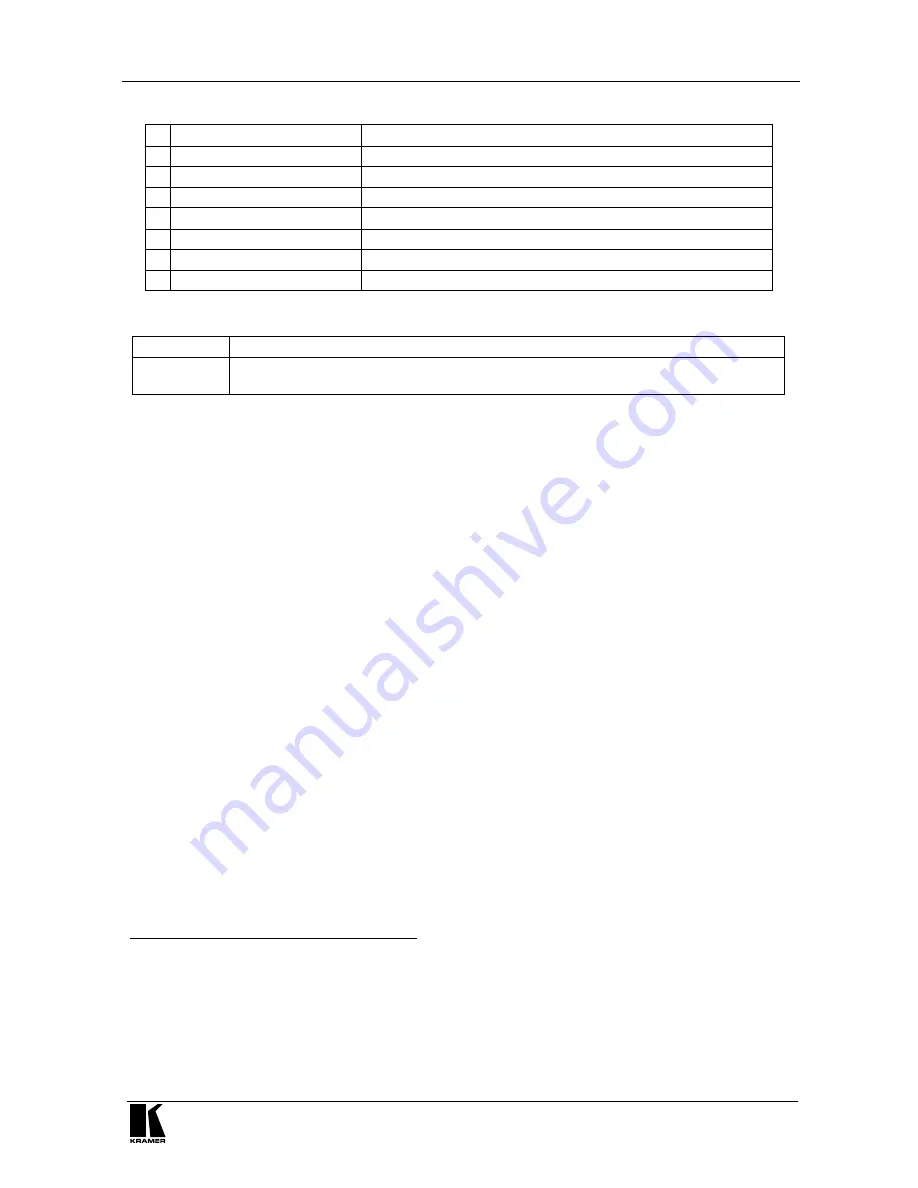
Table 1: Features and Functions of the VP-111 XGA Line Driver (Topside)
# Feature
Function
1
12V DC
+12V DC connector for powering the unit
2
OUTPUT
HD15F Connector Connect to the VGA/XGA acceptor
3
EQ.
Trimmer
Adjusts
1
the cable compensation equalization level for the output
4
TERM
Button
Pushing in selects
75
; releasing selects
Hi-Z
2
5
ON
LED
Illuminates when receiving power
6
LOOP
HD15F Connector
Connect to an additional monitor
7
INPUT
HD15F Connector
Connect to the VGA/XGA source
Table 2: Features and Functions of the VP-111 XGA Line Driver (Underside)
Feature
Function
ID Bit Switch
3
Sliding to the right selects the ID BIT, sliding to the left deactivates the ID BIT (when
outputting the input signal from a laptop connected to an external VGA monitor
4
)
5 Connecting the VP-111 XGA Line Driver
To connect the
VP-111
, as the example in Figure 2 illustrates, do the following:
1. Connect an XGA source (for example, a laptop’s graphics card) to the
INPUT HD15F connector.
2. On the underside, slide the ID Bit switch to the right to set to ON.
3. Connect the OUTPUT HD15F connector to the acceptor (for example, a
projector).
4. Connect the LOOP HD15F connector to a local PC monitor and release
the TERM button to Hi-Z.
Note: if only a single output is required, leave the loop unconnected and
push in the TERM button to 75 .
5. Connect the 12V DC power adapter to the power socket and connect the
adapter to the mains electricity.
6. Adjust
5
the video EQ. (equalization) compensation, if required.
1 Insert a screwdriver into the hole and carefully rotate it, to trim the level
2 For looping select Hi-Z
3 Illustrated in Figure 2
4 Sometimes laptop computers refuse to output a VGA signal to an external VGA monitor if they do not detect the ID Bit as
ON. Set the ID Bit to ON using this switch so that the laptop will output to an external VGA monitor
5 Insert a screwdriver into the small hole and carefully rotate it, trimming the OUTPUT equalization level