

The Kramer RC-5B2 and RC-5B4 Dual Inserts
Congratulations on purchasing your Kramer
RC-5B2
and
RC-5B4
dual inserts with RGB buttons,
which can be used as auxiliary controllers when connected via K-NET™ to a Master room controller
(for example, the
SV-552
SummitView™ Processor / Switcher
or one of the Kramer SL series
controllers).
K-NET is a proprietary Kramer protocol for communication between Kramer products.
The
RC-5B2
and
RC-5B4
packages include labels (P/N: 2808-300008) that are used as light
diffusers and therefore need to be inserted inside each button (even to “blank” buttons).
i
This user manual is written for the end user. Refer to the separate
K-Config
Configuration Guide (available online) for details of how to install and configure the
Room Controller. The guide provides information about how to set up the system
and is updated on a regular basis. For the latest online guide, go to
http://www.kramerelectronics.com/support/?soft=k-config
Defining the RC-5B2 and RC-5B4 Dual Inserts
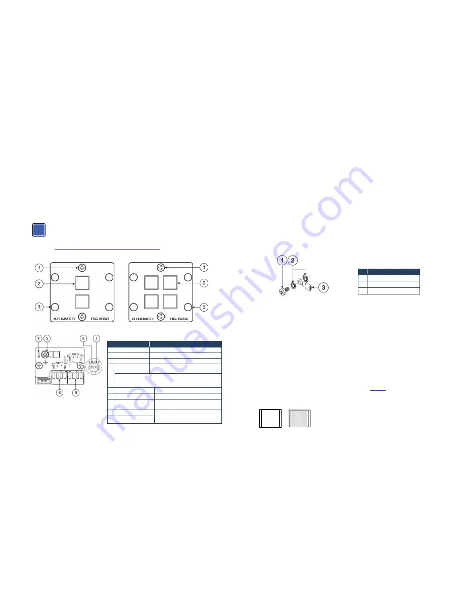
Figure 1: RC-5B2 and RC-5B4 Front Panel
Figure 2: RC-5B2 and RC-5B4 Rear Panel
#
Feature
Function
1 2 Faceplate Screws Remove to install labels
2 Front Panel Buttons Two/four programmable, backlit buttons
3 4 Screw Holes
For installing the insert
4 USB Connector
Connect to a computer for firmware upgrade
and for assigning a K-Net ID number
When the unit is connected via K-NET to a Master Room Controller,
you can upgrade the firmware via the USB or ETH ports of the Master
Room Controller
5 Grounding Screw
Connect to grounding wire
6
Prog. Switch
For factory use (internal switch)
7
TERM Switch
Switch to ON for K-NET line
termination (internal switch)
8 K-NET 1 Terminal Block Connect each terminal to the relevant one
on the Master K-Net unit or to another
AUX unit.
9 K-NET 2 Terminal Block
Overview
The
RC-5B2
and
RC-5B4
dual inserts are auxiliary remote control panels for Master Room
Controllers for control of A/V equipment in a room.
The
RC-5B2
and
RC-5B4
dual inserts feature:
•
Front panel, RGB backlit buttons: two for the
RC-5B2
and four for the
RC-5B4
7 colors are available for backlit buttons (to be configured by the system integrator).
•
Two K-NET ports and a USB serial port for setting the K-Net ID and for firmware upgrade
The
RC-5B2
and
RC-5B4
do not require a separate power supply.
Mounting the Kramer Insert
To mount a Kramer insert or connector module:
1. Place the Kramer insert over the opening.
2. Insert the four screws (two on each side) to fix the Kramer insert in place, and tighten them.
Grounding the RC-5B2 and RC-5B4
The grounding screw is used to earth the chassis of the unit to the ground of the building preventing
static electricity from impacting on the performance of the unit.
Figure 3: Grounding Connection Components
#
Component Description
1
M3X6 screw
2
1/8" Toothed Lock Washer
3
M3 Ring Tongue Terminal
To ground the RC-5B2 and RC-5B4:
1. Connect the Ring Tongue terminal to the building grounding point wire (it is recommended to
use a green-yellow AWG#18 (0.82mm2) wire, crimped with a proper hand-tool).
2. Insert the M3x6 screw through the toothed lock washers and the tongue terminal in the order
shown above.
3. Insert the M3x6 screw (with the two toothed lock washers and ring tongue terminal) into the
grounding screw hole and tighten the screw.
To install the button caps and labels:
1. Unscrew the two faceplate screws and remove the faceplate.
2. Remove the button cap.
3. Remove the required labels from the supplied button label sheet.
4. Hold the button cap so that it is oriented as shown in
Figure 4
with the “wings” on the left and
right sides.
5. Insert the label inside the cap
ON
Figure 4: Button Cap Orientation Before and After the Insertion of a Label
6. Repeat for all caps.
im Vertrieb von
CAMBOARD Electronics
www.camboard.de
Tel. 07131 911201
Fax 07131 911203


