


Kramer Electronics Ltd.
PT-871/2-KIT, PT-871/2xr-KIT, WP-871xr, WP-872xr, PT-871xr, PT-872xr
– Defining PT-871/2-KIT, PT-
871/2xr-KIT, WP-871xr, WP-872xr, PT-871xr, PT-872xr
4
Defining PT-871/2-KIT, PT-
871/2xr-KIT, WP-871xr, WP-
872xr, PT-871xr, PT-872xr
PT-871/2-KIT
includes PT-871 and PT-872.
PT-871/2xr-KIT
includes PT-871xr and PT-
872xr.
PT-871
PT-872
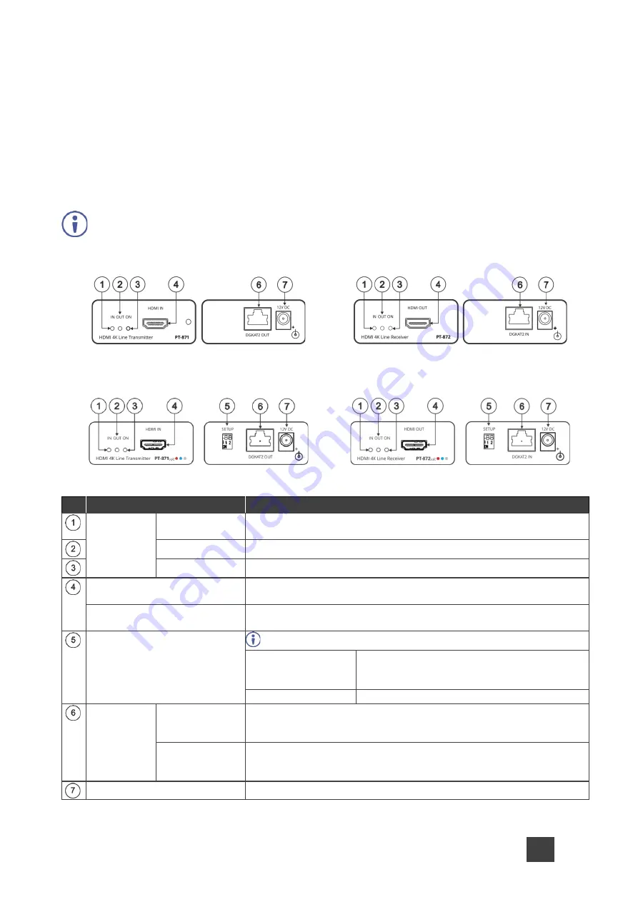
Figure 1:
PT-871
Line Transmitter
Figure 2:
PT-872
Line Receiver
PT-871xr
PT-872xr
Figure 3:
PT-871xr
Line Transmitter
Figure 4:
PT-872xr
Line Receiver
#
Feature
Function
LED
Indicators
IN
Lights when an active source is connected to HDMI IN on the
transmitter.
OUT
Lights when an active acceptor is connected to HDMI OUT on the receiver.
ON
Lights when power is connected to the device.
HDMI IN Connector
(
PT-871, PT-871xr
)
Connect to an HDMI source.
HDMI OUT Connector
(
PT-872, PT-872xr
)
Connect to an HDMI acceptor.
SETUP DIP-switches
(
PT-871xr, PT-872xr
)
Always set DIP-switch 1 identically on both devices.
DIP-switch 1:
Compression Options
OFF (up)
– Standard compression level (default).
ON (down)
– High compression level for
additional range extension.
DIP-switch 2:
Must be set to OFF (up).
DGKAT2
RJ-45
Connector
OUT
(
PT-871, PT-
871xr
)
Connect to the DGKat-2.0 IN connector on the
PT-872xr
using twisted
pair cable.
IN
(
PT-872, PT-
872xr
)
Connect to the DGKat-2.0 OUT connector on the
PT-871xr
using
twisted pair cable.
12V DC Connector
Connect to the power adapter of one of the devices.