


Kramer Electronics Ltd.
KT-107, KT-107RB - Defining the KT-107, KT-107RB
8
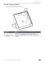
KT-107 On-Wall Mount
This section defines the
KT-107
on-wall mount
.
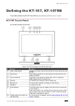
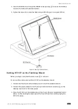
Figure 5: KT-107 Touch Panel Front Panel
#
Feature
Function
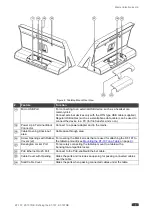
Groove (x4)
For hanging the panel mount plate (attached to
KT-107
) on a wall.
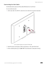
Flat Cable Connector
Connect to the rear side of the
KT-107
using the supplied flat cable
.
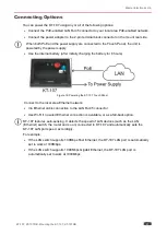
Passes the Ethernet signal and power to the
KT-107
.
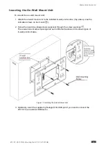
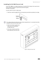
Screw Opening (x8)
For attaching the on-wall mount unit to a standard in-wall junction box
(various holes fit different standard in-wall junction boxes), see
Unit Cable Opening
Pass the supplied right-angle OTG USB cable through the opening to connect
to the rear side of the
KT-107
.
Indication Arrows
Top side up; shows the correct direction for mounting the on-wall mount unit
and for hanging the
Touch Panel
.
Screw Opening (x2)
For attaching the on-wall mount unit to a standard in-wall junction box
(various holes fit different standard in-wall junction boxes.
Indication Arrows
Top side up; shows the correct direction for hanging the panel mount plate.
Plate Cable Opening
Fits the opening on the on-wall mount unit. Pass the right-angle OTG USB
cable through the opening to connect to the rear side of the
KT-107
.
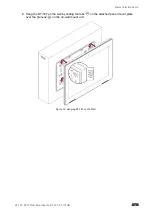
Screw opening (x4)
Attach the
KT-107
to the panel mount plate using the supplied screws.
Cable opening
Pass the cables through the opening to connect to the rear side of the
KT-107
.
Tab (x4)
For hanging the
KT-107
with the attached panel mount plate on the on-wall
mount unit.


