background image

Kramer Electronics Ltd. 


KDS-SW2-EN7 

– Using KDS-SW2-EN7 Embedded Web Pages 

32 


KDS-SW2-EN7 Network Settings 

The device enables performing the following actions: 


Defining Interface Settings

 on page 

32

. 


Defining IP Casting Mode Setting

 and TTL on page 

33

. 


Managing TCP/UDP Ports

 on page 

33

. 

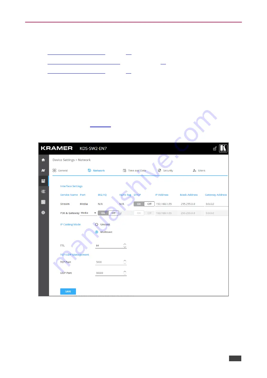
Defining Interface Settings 

Define interface settings for each of the Ethernet ports. 

To define interface settings: 

1.  In the Navigation pane, Select 

Device Settings

. The General tab in the Device Settings 

page appears (see 

Figure 18

)

2.  Select the 

Network

 tab. The Network tab appears. 


Figure 19: Device Settings Page 

– Network Tab 

3.  Set the Media port Stream service parameters: 


DHCP mode


– Set DHCP to 

On

 (default) or 

Off


IP Address


– When DHCP mode is set to Off, the device uses a static IP address. 

This requires entering mask and gateway addresses. 


Mask Address


– Enter subnet mask. 

Summary of Contents for KDS-SW2-EN7

Page 1: ...P N 2900 301561 Rev 1 www kramerAV com USER MANUAL MODEL KDS SW2 EN7 4K AVoIP Encoder...

Page 2: ...oss Timeouts 22 Defining HDMI Input Settings 23 Defining Audio Settings 25 Managing EDID 27 General Device Settings 28 KDS SW2 EN7 Network Settings 32 Defining KDS SW2 EN7 Time and Date 34 Setting KDS...

Page 3: ...ramer high performance high resolution cables to avoid interference deterioration in signal quality due to poor matching and elevated noise levels often associated with low quality cables Do not secur...

Page 4: ...2 or CEC signals via Ethernet over copper cable in unicast one to one or multicast one to many configurations KDS SW2 EN7 encodes and streams the video signal from one of two selectable inputs and tra...

Page 5: ...oses Flexible Connectivity Selectable Inputs 1 HDMI and 1 USB C input Analog embedded audio inputs and outputs Plug and play with Netgear M4250 AVoIP switches Kramer Control KDS USB2 etc Typical Appli...

Page 6: ...anges LINK LED See Understanding LED Functionality on page 9 NET LED ON LED 24V 5A DC Connector Connect to the power adapter purchased separately RESET Recessed Button Press and hold for 10 seconds to...

Page 7: ...for bi directional signal extension even when no AV signal is extended Expected voltage for IR receiver 3 3V USB Type A Charging Ports 1 and 2 Connect to USB devices for example to a speakerphone and...

Page 8: ...r flow is compatible for the device Avoid uneven mechanical loading Appropriate consideration of equipment nameplate ratings should be used for avoiding overloading of the circuits Reliable earthing o...

Page 9: ...in the example in Figure 2 1 Connect an HDMI source for example a server or a media player to the HDMI IN connector on the KDS SW2 EN7 2 Connect a video source for example a laptop to the USB IN conne...

Page 10: ...er side to the IR sensor of the display 9 Connect RS 232 3 pin terminal block connectors On the KDS SW2 EN7 connect the RS 232 port to a laptop controller On the KDS DEC7 connect RS 232 to the display...

Page 11: ...Flashes Green Slowly Device is in standby mode Flashes green fast FW is downloaded in the background Flashes Green very fast for 60sec A device identification command is sent Flag me Lights Yellow Dev...

Page 12: ...tered Multicast Filtering On Using Menu Navigation Buttons Connect the device to the 24V DC power adapter and connect the adapter to the mains electricity The ON LED lights green and the LINK LED flas...

Page 13: ...ddress Subnet mask and Gateway address LAN2 STATUS including IP address Subnet mask and Gateway address HDMI STATUS including video input resolution and HDCP settings status View Device channel ID CH...

Page 14: ...ttons To define HDCP settings 1 Press the left or right arrows to access the HDCP Settings menu 2 Press the up or down buttons to select HDMI IN or USB C IN inputs 3 For each selected input press the...

Page 15: ...LCD screen menu Setting Channel Number Each encoder requires a unique channel number and the connected decoders should be tuned to that encoder channel You can set the channel number via the LCD scree...

Page 16: ...eb UI By default IP setting for KDS SW2 EN7 is DHCP To access the Web UI perform the following 1 Connect the LAN port of the device to a local area network Make sure that there is a DHCP server in the...

Page 17: ...connect to the device and click Change settings of this connection The Local Area Connection Properties window for the selected network adapter appears as shown in Figure 7 Figure 7 Local Area Connect...

Page 18: ...ties Window Figure 9 Internet Protocol Version 6 Properties Window 6 Select Use the following IP Address for static IP addressing and fill in the details as shown in Figure 10 For TCP IPv4 you can use...

Page 19: ...indow 7 Click OK 8 Click Close Connecting Ethernet Port via a Network Hub or Switch You can connect the Ethernet port of KDS SW2 EN7 to the Ethernet port on a network hub or using a straight through c...

Page 20: ...Chrome Mac Safari iOS Safari Android N A Some features might not be supported by some mobile device operating systems KDS SW2 EN7 enables performing the following Defining AV Routing Parameters on pag...

Page 21: ...f the device in the Address bar of your browser For example the default IP number The Login window appears Figure 11 Login Window 3 Enter the Username and Password Admin Admin by default The KDS SW2 E...

Page 22: ...0 Default is 80 0dB 100 12dB and 0 is mute Mute Mute unmute all audio outputs HDMI OUT AUDIO OUT and MEDIA ports Play Stop Start or stop streaming of video audio IR RS 232 and USB signals 4 View the f...

Page 23: ...put to high or low the input with the high priority is switched first In the following example USB IN2 is dragged to the High priority location and replaces HDMI IN1 which moves to the Low priority lo...

Page 24: ...Signal Detection Delay From the time KDS SW2 EN7 detects a signal to when it switches to that input default 0 Cable Plug Delay From the time KDS SW2 EN7 detects a cable connected to when it switches t...

Page 25: ...AV The Auto Switch tab in the AV Routing page appears see Figure 13 Figure 15 AV Settings Page Video Tab 2 Define the following settings Input 1 2 enable ON disable OFF HDCP support for each input or...

Page 26: ...and 200Mbps or Best Effort default to set bandwidth for best video quality output allowing the peak bandwidth to reach 850Mbps After setting the maximum bit rate you need to restart the device Maximum...

Page 27: ...ch tab in the AV Settings page appears see Figure 13 2 Select the Audio tab The Audio tab appears Figure 16 AV Settings Page Audio Tab 3 Select IN or OUT to select the audio direction If IN is selecte...

Page 28: ...its priority order The device switches the highest priority audio input to the output Manual manually select the audio source The device switches an audio source only when selected manually 5 Set the...

Page 29: ...required To manage EDID 1 In the Navigation pane Select AV The Auto Switch tab in the AV Routing page appears see Figure 13 2 Select the EDID tab The EDID Management tab appears Figure 17 AV Settings...

Page 30: ...st Click REMOVE To upload an EDID file Click UPLOAD Select an EDID file from the Open window Click UPLOAD the EDID file is added to the list Select the file and click UPLOAD You can load up to 8 EDID...

Page 31: ...rnet ports in two subnets using one MAC address see KDS SW2 EN7 Network Settings on page 32 KDS SW2 EN7 enables performing the following actions via the General Settings tab Locking Unlocking the Fron...

Page 32: ...e Settings page appears Figure 18 Device Settings General Tab 2 Lock Unlock the device front panel Click On to lock the front panel buttons and disable device control via the navigation buttons Click...

Page 33: ...RT An Open file appears Select the file to import settings tar gz Click Open to import the file 4 To export settings click EXPORT The settings file is created settings tar gz The settings file is impo...

Page 34: ...ace settings for each of the Ethernet ports To define interface settings 1 In the Navigation pane Select Device Settings The General tab in the Device Settings page appears see Figure 18 2 Select the...

Page 35: ...VLAN Tag Enter an integer number to specify a VLAN ID 2 4093 to P3K Gateway services This way the P3K Gateway service will have the VLAN packets tagged to Network DHCP mode Set DHCP to On default or O...

Page 36: ...ick Device Settings The General tab in the Device Settings page appears see Figure 18 2 Select the Time and Date tab The Time and Date tab appears Figure 20 Device Settings Page Time and Date Tab 3 Ne...

Page 37: ...nticated peer over the network This section describes the following actions Configuring HTTPS on page 35 Defining 802 1x Authentication on page 36 Contact your IT administrator for the network access...

Page 38: ...ure 22 Security Tab Server Certificate 5 Click APPLY HTTPS is configured Defining 802 1x Authentication To configure security 1 In the Navigation pane click Device Settings The General tab in the Devi...

Page 39: ...it certificate from the server for authentication To do so enter the Username click to upload the certificates and keys and enter the private key password assigned by IT administrator Set Server Certi...

Page 40: ...upon initial landing on operation page The default password is admin By default security is disabled Enabling User Access To enable security 1 In the Navigation pane click Device Settings The General...

Page 41: ...ser Access To enable security 1 In the Navigation pane click Device Settings The General tab in the Device Settings page appears see Figure 18 2 Select Users tab see Figure 25 Figure 27 Device Setting...

Page 42: ...neral tab in the Device Settings page appears see Figure 18 2 Select Users tab see Figure 25 3 Set security Status to On Figure 29 Device Settings Users Tab 4 Next to Old Password enter the old passwo...

Page 43: ...s from a control system connected by LAN via the KDS SW2 EN7 built in control gateway to control CEC enabled devices that are connected to the KDS SW2 EN7 HDMI output and input To set CEC Gateway 1 In...

Page 44: ...d to the KDS SW2 EN7 RS 232 port To set RS 232 Gateway 1 In the Navigation pane click Control The Control Settings page appears see Figure 30 Figure 31 Control Settings Page RS 232 Settings 2 Click En...

Page 45: ...in control gateway to IR connected devices To set RS 232 Gateway 1 In the Navigation pane click Control The Control Settings page appears Figure 32 Control Settings Page IR Settings 2 Set IR direction...

Page 46: ...ication 3 View device internal heat status Normal for temperatures under 45 C green indication High for temperatures between 45 C and 60 C orange indication Overheat for temperatures higher than 60 C...

Page 47: ...nection information status To view Connections status 1 In the Navigation pane click Diagnostics The Status tab appears see Figure 33 2 Select the Connections tab Figure 34 Diagnostics Status Tab 3 Vi...

Page 48: ...click Diagnostics The Status tab appears see Figure 33 2 Select the Advanced tab Figure 35 Diagnostics Advanced Tab 3 Define Syslog activity On to enable device system log locally Off default to disab...

Page 49: ...ronics Ltd KDS SW2 EN7 Using KDS SW2 EN7 Embedded Web Pages 47 Viewing the About Page View the web page hardware release firmware version and Kramer Electronics Ltd details in the About page Figure 36...

Page 50: ...W2 EN7 and KDS DEC7 and PC are all connected to the same Network 2 Power all the devices in the system 3 Configure the Network switch as follows Jumbo Frames On at least 8000 bytes IGMP Snooping On IG...

Page 51: ...hosts via USB from one master KDS DEC7 decoder connected to a keyboard and mouse see for example the following layout Figure 37 KVM Roaming Layout To configure KVM roaming 1 Access the encoder and dec...

Page 52: ...der For example pair ENC 1 to DEC 1 ENC 2 to DEC 2 ENC 3 to DEC 3 and ENC 4 to DEC 4 Figure 39 KDS DEC7 Setting Channel ID and Name 4 For the Decoder that has the keyboard and mouse connected open the...

Page 53: ...2x2 video wall set Row to 2 and Column to 2 Figure 41 Setting the decoder configuration 7 Check the physical location of the Master decoder lower left size in this example The MAC address is automatic...

Page 54: ...et a unique Channel ID and name Figure 43 Setting Channel ID and Name on the KDS SW2 EN7 Devices 3 Make sure that all the encoders in the system share the same settings For example to configure fast s...

Page 55: ...tech support team at support kramerav com or go to our Web site at k kramerav com support downloads asp To upgrade the firmware 1 In the Navigation pane Select Device Settings The General tab in the D...

Page 56: ...nel LCD Display Rear Panel Restart and factory reset button Controls Embedded web pages P3K API commands via Ethernet front panel navigation buttons Power Options PoE on LAN PoE port Consumption 24V D...

Page 57: ...01 02 3A 80 D0 72 38 2D 40 10 2C 40 45 80 20 C2 31 00 00 1E E7 31 80 A0 70 B0 1D 40 50 30 20 36 00 59 32 00 00 00 1A 00 00 00 F7 00 0A 60 00 4A A2 24 02 00 00 00 00 00 00 00 00 00 00 FC 70 00 4B 44 5...

Page 58: ...1024 60 Hz 1360 x 768 60 Hz 1440 x 900 60 Hz 1400 x 1050 60 Hz 1680 x 1050 60 Hz 1600 x 1200 60 Hz 1920 x 1200 60 Hz RB Descriptor Block Display Product Name Value KDS7 Encoder Block 1 0 1 2 3 4 5 6 7...

Page 59: ...bit IEEE Registration ID 0xC45DD8 HDMI Forum Vendor Specific Data Block Version 1 Max_TMDS_Character_Rate 300 MHz Max FRL Rate Not Supported Y SCDC_Present N RR_Capable N CABLE_STATUS N CCBPCI N LTE_...

Page 60: ...Off Network Stream Port No Yes Media Stream 802 1Q No Yes N A Stream VLAN Tag No Yes N A Stream DHCP Yes Yes On P3K Gateway Port Yes Yes Media P3K Gateway 802 1Q Yes Yes Off P3K Gateway VLAN Tag Yes Y...

Page 61: ...ommand Parameter CR LF Command parameters Multiple parameters must be separated by a comma In addition multiple parameters can be grouped as a single parameter using brackets and Command chain separat...

Page 62: ...command to be to be sent to HDMI Input 2 CEC Gateway mode command to be to be sent to HDMI Output 3 CEC Gateway mode command to be sent to HDMI Loop Through Set CEC Gateway mode CEC GW PORT ACTIVE 1...

Page 63: ...TOM DEFAULT Index for CUSTOM get index from EDID LIST command Set EDID to custom mode idx is 1 EDID MODE 1 CUSTOM 1 CR EDID MODE Get EDID work mode EDID MODE Input_id CR nn EDID MODE Input_id Mode Ind...

Page 64: ...status Signal encryption status valid values On Off 0 HDCP Off 1 HDCP On Get the output HDCP STATUS of IN 1 HDCP STAT 0 1 CR HELP Get command list or help for specific command HELP CR HELP cmd_name CR...

Page 65: ...n KDS GW ETH gw_type netw_id CR LF gw_type 0 Control netw_id Network ID the device network interface 0 Media Port 1 Service Set network port gateway to Service KDS GW ETH 0 1 CR KDS GW ETH Get gateway...

Page 66: ...7Hz 30Hz 35 2880x480p 59 94Hz 60Hz 36 2880x480p 59 94Hz 60Hz 37 2880x576p 50Hz 38 2880x576p 50Hz 39 1920x1080i 50Hz 40 1920x1080i 100Hz 41 1280x720p 100Hz 42 720x576p 100Hz 43 720x576p 100Hz 44 720 14...

Page 67: ...e LOCK FP CR nn LOCK FP lock unlock CR LF Lock Unlock On Off Off Unlocks EDID On Locks EDID Get the front panel lock state LOCK FP CR LOG ACTION Reset events log LOG ACTION action period CR nn LOG ACT...

Page 68: ...This command identifies equipment connected to KDS SW2 EN7 and notifies of identity changes to the connected equipment The Matrix saves this data in memory to answer REMOTE INFO requests MODEL CR nn...

Page 69: ...omitted In this case the Network ID by default is 0 which is the Ethernet control port NET DHCP netw_id dhcp_state CR nn NET DHCP netw_id dhcp_state CR LF netw_id Network ID the device network interf...

Page 70: ...nal_type Signal ID attribute AUDIO IR direction Port direction IN Input OUT Output Set audio analog port direction as input PORT DIRECTION both analog 1 audio IN CR PORT DIRECTION Get port direction P...

Page 71: ...NDBY TIMEOUT 10 CR STANDBY TIMEOUT Get inactivity auto standby time STANDBY TIMEOUT CR nn STANDBY TIMEOUT time CR LF time minutes of standby time Get Inactivity auto standby time STANDBY TIMEOUT CR ST...

Page 72: ..._bits 1 5 is only relevant for 5 data_bits UART com_id baud_rate data_bits parity st op_bits_mode serial_type 485_term CR nn UART com_id baud_rate data_bits pa rity stop_bits_mode serial_type 485_term...

Page 73: ...mat Type of signal on the port HDMI USB_C STREAM ANALOG_AUDIO RS 232 IR USB_A USB_B port_index The port number as printed on the front or rear panel 1 HDMI IN 2 USB_C IN 1 HDMI OUT signal_type Signal...

Page 74: ...x CR nn X AV SW MODE direction_type port_format port_index signal_type index connection_mode CR LF The following attributes comprise the signal ID direction_type Direction of the port IN Input OUT Out...

Page 75: ...X PRIORITY direction_type port_format port_index signal_type direction_type port_format port_index signal_type CR LF direction_type Direction of the port IN Input OUT Output BOTH Bi directional port_...

Page 76: ...ommand X ROUTE direction_type1 port_type1 po rt_index1 signal_type1 index1 CR nn X ROUTE direction_type1 port_type1 port_index1 signal_type1 index1 direction_type2 port_type2 port_index2 s ignal_type2...

Page 77: ...t enough space for data firmware FPGA ERR_FS_NOT_ENOUGH_SPACE 11 Not enough space file system ERR_FS_FILE_NOT_EXISTS 12 File does not exist ERR_FS_FILE_CANT_CREATED 13 File can t be created ERR_FS_FIL...

Page 78: ...ized dealer from which it was purchased or any other party authorized to repair Kramer Electronics products this product must be insured during shipment with the insurance and shipping charges prepaid...

Page 79: ...nd a list of Kramer distributors visit our website where updates to this user manual may be found We welcome your questions comments and feedback The terms HDMI HDMI High Definition Multimedia Interfa...

Reviews: