


K-CONFIG –
Planning the Controlled Room
3
2
Planning the Controlled Room
You are here:
Configuration Steps
Description
Section
Introduction
General information and system requirements
Planning
Carefully plan your controlled room
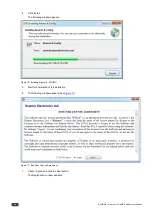
Installation
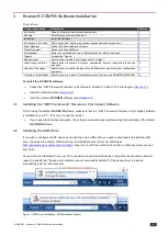
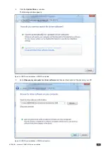
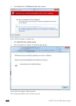
Install the Software
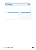
Introduction to K-Config
Get to know the K-Config main window, menus and quick access icons
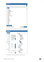
Driver Manager
Define the Controlled Device Drivers
Project Navigator
Define the Controlled Room
Port Manager
Assign the controlled devices to the Master and Auxiliary device ports
Triggers
Activate the Triggers
Adding Actions
Describes how to add the various actions to a trigger
Connecting to a Device
Describes how to connect to a device, upgrade the firmware, read/write to the device
and so on
Using the Web pages
Describes how to control the device via the Ethernet and perform minor configuration
operations
Creating a Virtual Master
Describes how to create a Virtual Master to control a room via KRAMER NETWORK
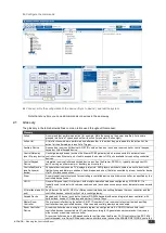
Carefully plan your room controller system layout to ensure smooth configuration and installation of the system. The
following table summarizes the basic configuration and installation steps:
Stage
K-Config Tool
Description
Plan
List room devices, location, connectivity and main commands
Install HW system
Connect room AV, Lighting, Automation and Control system
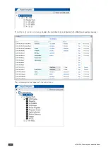
Set SW drivers
Driver Manager
Get device drivers and set proper device commands and responses
Set control SW system
Project Navigator and
Port Manager
Set controllers, keypads and gateways
Assign control ports connectivity to controlled devices
Configure control SW
program
Triggers and Action
Editor
Assign commands & actions to UI and triggering events
Activate control system
Connect
Sync control SW program to HW system
Validate proper control system operation
The following are the steps that will get you going:
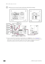
A:
Define the room requirements; list the items required, plan the location and function of the devices; prepare a
detailed list of the functions and commands required of the system devices:
Device
Function
Connected to
Sample Commands
Projector
Main room display
RS-232
On/off, input selecting, blank, freeze, menu, and so
on
LCD Display
Local Monitor
RS-232
On/off, input selecting, volume, aspect ratio, Freeze,
Menu, and so on
Laptop
Input the lecturer’s laptop Ethernet
Use the RC’s Web page, perform “Test command”
when installing the RCs in the room.
VP-81SIDN
Inputs of different user
RS-485
Select input, mute, volume, and so on
VP-771
Select a source
Ethernet
Input selecting, PIP, Blank, mute and so on
DVD Player
Input the DVD Player
IR
On/off, play/stop and so on
Power Amplifier
Amplify the volume
IR
On/Off, volume, select input, mute on/off, and so on
Projector Screen
Roll down and roll up
Relay
Up, down
Lighting System
Set the lights
Relay
On, off, dim
Motion detector
Burglar detection
GPI/O
Other functions you would like to have in the room include general command sequences such as weekend shutdown,
room startup and so on.


