background image


Step 1: Check what’s in the box

VS-30FW Quick Start Guide

Step 2: Install the VS-30FW

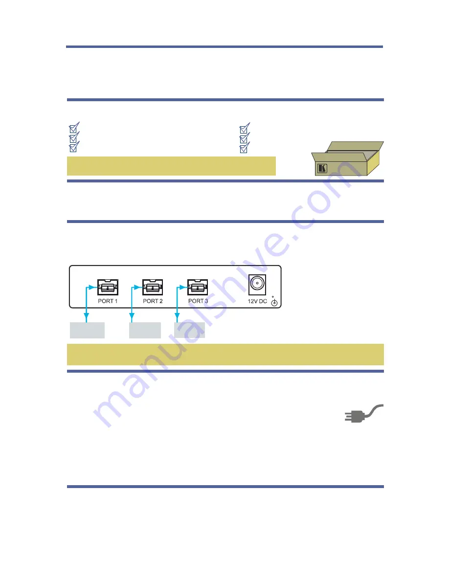
Step 3: Connect the inputs and outputs


Mount the machine in a rack (using the RK-2TB rack adapter) or place on a table.


This page guides you through a basic installation and first-time use of your 

For more detailed information, see 

VS-30FW

the 

 user manual. You can download the latest 

manual at 

.

VS-30FW

http://www.kramerelectronics.com

Save the original box and packaging materials in case your Kramer 

product needs to be returned to the factory for service.

Always switch off the power on each device before connecting it to your 

VS-30FW

For best results, we recommend that you always use Kramer high-performance  cables to 

connect AV equipment to the 

.

VS-30FW

The 

 FireWire 800/1394b Repeater/HUB

1 12V DC power adapter (12V, 500mA)

VS-30FW

4 rubber feet and mounting bracket

1 Quick start sheet

1 User Manual

FireWire® cable (C-FM9/FM9-3)

PC (via FW)

Video 

Camcorder

Step 4: Connect the power

Connect the 12V DC power adapter to the 

 and plug the adapter into the mains 

electricity.

VS-30FW

Hard Drive

Each FireWire device can derive its power in one of two ways:

VS-30FW

VS-30FW

VS-30FW

VS-30FW

Independently, by connecting each FireWire device to its own power supply, while the 

 is connected to the external 12VDC (12V, 500mA) power supply.

Via the 

 that is connected to an external powerful power supply: the 12VDC 

(12V, 2.1A) (optional with the 

). In this case, each of the (up to) 3 FireWire devices 

can derive its power (up to 1A per port) from the respective 

 FireWire port.

Summary of Contents for FireWire VS-30FW

Page 1: ... ...

Page 2: ...se Kramer high performance cables to connect AV equipment to the VS 30FW The FireWire 800 1394b Repeater HUB 1 12V DC power adapter 12V 500mA VS 30FW 4 rubber feet and mounting bracket 1 1 Quick start sheet 1 User Manual FireWire cable C FM9 FM9 3 PC via FW Video Camcorder Step 4 Connect the power Connect the 12V DC power adapter to the and plug the adapter into the mains electricity VS 30FW Hard ...

Page 3: ...eater HUB 3 3 2 FireWire Compliance 5 4 Defining the VS 30FW FireWire 800 1394b Repeater HUB 6 5 Using the VS 30FW FireWire 800 1394b Repeater HUB 7 5 1 Powering the FireWire Devices 8 6 Technical Specifications 9 Figures Figure 1 VS 30FW FireWire 800 1394b Repeater HUB Front and Rear Panels 6 Figure 2 Connecting the VS 30FW FireWire 800 1394b Repeater HUB 7 ...

Page 4: ... different models now appear in 11 groups that are clearly defined by function GROUP 1 Distribution Amplifiers GROUP 2 Switchers and Matrix Switchers GROUP 3 Control Systems GROUP 4 Format Standards Converters GROUP 5 Range Extenders and Repeaters GROUP 6 Specialty AV Products GROUP 7 Scan Converters and Scalers GROUP 8 Cables and Connectors GROUP 9 Room Connectivity GROUP 10 Accessories and Rack ...

Page 5: ...re appropriate 2 1 Achieving the Best Performance To achieve the best performance Use only good quality connection cables to avoid interference deterioration in signal quality due to poor matching and elevated noise levels often associated with low quality cables Avoid interference from neighboring electrical appliances that may adversely influence signal quality Position your Kramer VS 30FW away ...

Page 6: ...tatic discharge that can damage digital equipment Alternate Power Sources Can be powered from the 12V DC power supply or through the PC connection Requires 9 Pin FireWire 800 Cable Compact Kramer TOOLS 3 units can be rack mounted side by side in a 1U rack space with the optional RK 3T rack adapter 3 1 About the VS 30FW FireWire 800 1394b Repeater HUB Many computers today come with one or more Fire...

Page 7: ...f the devices Sometimes it is possible that a computer can work with many FireWire devices simultaneously like a distributor sometimes it can work with many devices in time sharing mode like a switcher But most often it is possible to work one to one In this case you have to disconnect all the devices that are unnecessary at this time and leave only two of them Since the FireWire is hot plug stand...

Page 8: ...1 Gigabit signaling rates Fully supports the provisions of the IEEE 1394 1995 Standard for High Performance Serial Bus and the P1394a Supplement Is fully interoperable with FireWire and i LINK implementation of IEEE Std 1394 Provides three fully backward compatible 1394a 2000 fully compliant bilingual P1394b cable ports at up to 800 Megabits per second Mbits s Is fully compliant with OpenHCI requi...

Page 9: ...4b Repeater HUB Front and Rear Panels Feature Function 1 PORT 1 Connects to the FireWire device 1 2 PORT 2 Connects to the FireWire device 2 3 PORT 3 Connects to the FireWire device 3 4 12V DC 12V DC connector for powering the unit 5 ON LED Illuminates when receiving power 6 ACTIVE LED Lights when a connection between 2 FireWire devices is established ...

Page 10: ...o a video camcorder PORT 2 to a hard drive and PORT 3 to a computer Not all ports need to be connected Any unused port should simply be left unconnected 2 Connect the 12V DC power adapter to the power socket and connect the adapter to the mains electricity not shown in Figure 2 The ON red LED lights 3 Be sure that the power on each device is turned ON The ACTIVE green LED lights indicating that th...

Page 11: ... FireWire device to its own power supply while the VS 30FW is connected to the external 12VDC 12V 500mA power supply supplied with the VS 30FW Via the VS 30FW that is connected to an external powerful power supply the 12VDC 12V 2 1A optional with the VS 30FW In this case each of the up to 3 FireWire devices can derive its power up to 1A per port from the respective VS 30FW FireWire port ...

Page 12: ...IEEE P1394a IEEE P1394b POWER SOURCE 12V DC 500mA or from the attached PC DIMENSIONS 12cm x 7 5cm x 2 5cm 4 7 x 2 95 x 0 98 W D H WEIGHT 0 3kg 0 67lbs approx ACCESSORIES Power supply FireWire cable C FM9 FM9 3 mounting bracket OPTIONS RK 3T 19 rack adapter Specifications are subject to change without notice Go to our Web site at http www kramerelectronics com to access the list of resolutions ...

Page 13: ...of nature ii Product modification orfailure to follow instructions supplied withtheproduct iii Repair orattemptedrepairby anyone not authorized by Kramer iv Any shipment of theproduct claims must bepresentedtothe carrier v Removal orinstallation of theproduct vi Any other cause which does not relate to aproduct defect vii Cartons equipment enclosures cables or accessories used inconjunction withth...

Page 14: ...tributors visit our Web site where updates to this user manual may be found We welcome your questions comments and feedback Web site www kramerelectronics com E mail info kramerel com SAFETY WARNING Disconnect the unit from the power supply before opening and servicing ...

Reviews: