


Configuring the FC-8 Wi-Fi - RS-232 Bridge
11
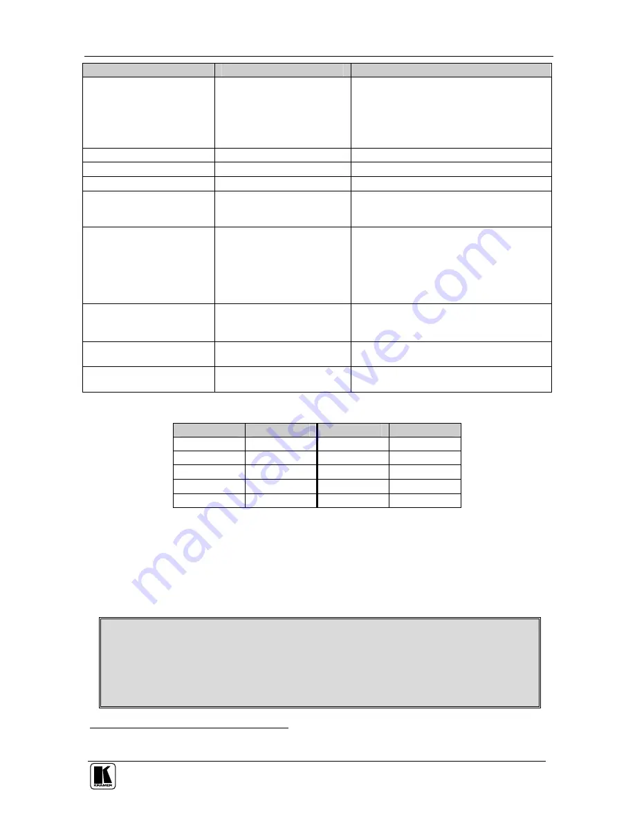
Parameter
Possible Values
Notes
Wireless LAN WEP Key1
WEP64 – no more than 10
characters (5 bytes) allowed
(hex 0-9 A-F)
WEP128 – no more than 26
characters (13 bytes)allowed
(hex 0-9 A-F)
Wireless LAN WEP Key2
Same as WEP Key1
Wireless LAN WEP Key3
Same as WEP Key1
Wireless LAN WEP Key4
Same as WEP Key1
Pre-shared Key Passphrase WPA – ASCII string must be
between 8-63 alphameric
characters
SerialNet Serial Parameters <b, d, p, s, f >
5, 8, N, 1, 0 (Default)
Where:
b = baud [1–9 or h] (see
Table 4
)
d = data bits [7 or 8]
p = parity [N, E, O]
s = stop bits [1]
f = flow [0, 1]
Default IP
192.168.3.2
Set to 0.0.0.0 to receive IP
address from a DHCP server
Factory default address
[Submit]
Enters the changes made in the
configuration table
[Refresh]
Redisplays values of the configuration
screen
Table 4: Baud Rate Settings
Baud Code
Baud Rate
Baud Code
Baud Rate
1
600
6
19200
2
1200
7
38400
3
2400
8
57600
4
4800
9
115200
5
9600
h
230400
2. Change the parameters as needed to attach the
FC-8
to the new network and
press
Submit
.
Important:
When changing the IP address, input the same new address into
both the Active IP Address field and in Default IP field.
Note:
It may take a few minutes for the update to complete.
Warning
: You must enter the correct network parameters. If the parameters
are incorrect, the network will not recognize the unit and you will not be able to
access the device until it is reconfigured using a special program
1
, which can
be downloaded from the Kramer Web site.
1 The
FC-8
must be connected to a PC over the serial port while running the program
Summary of Contents for FC-8
Page 1: ...Kramer Electronics Ltd USER MANUAL Model FC 8 Wi Fi RS 232 Bridge...
Page 2: ......
Page 4: ......
Page 18: ...14...