

FC-28
Quick Start
P/N: 2 9 0 0 - 3 0 1 2 7 9 QS
Rev: 3
Scan for full manual
FC-28 Quick Start Guide
This guide helps you install and use your
FC-28
for the first time.
www.kramerav.com/downloads/FC-28
to download the latest user manual and check if firmware
upgrades are available.
Step 1: Check
what’s in the box
FC-28
Ethernet Controller
1 Bracket set
4 Rubber feet
1 IR cable (C-A35M/RE-10)
1 Power supply 5V DC
1 Quick start guide
Step 2: Get to know your FC-28
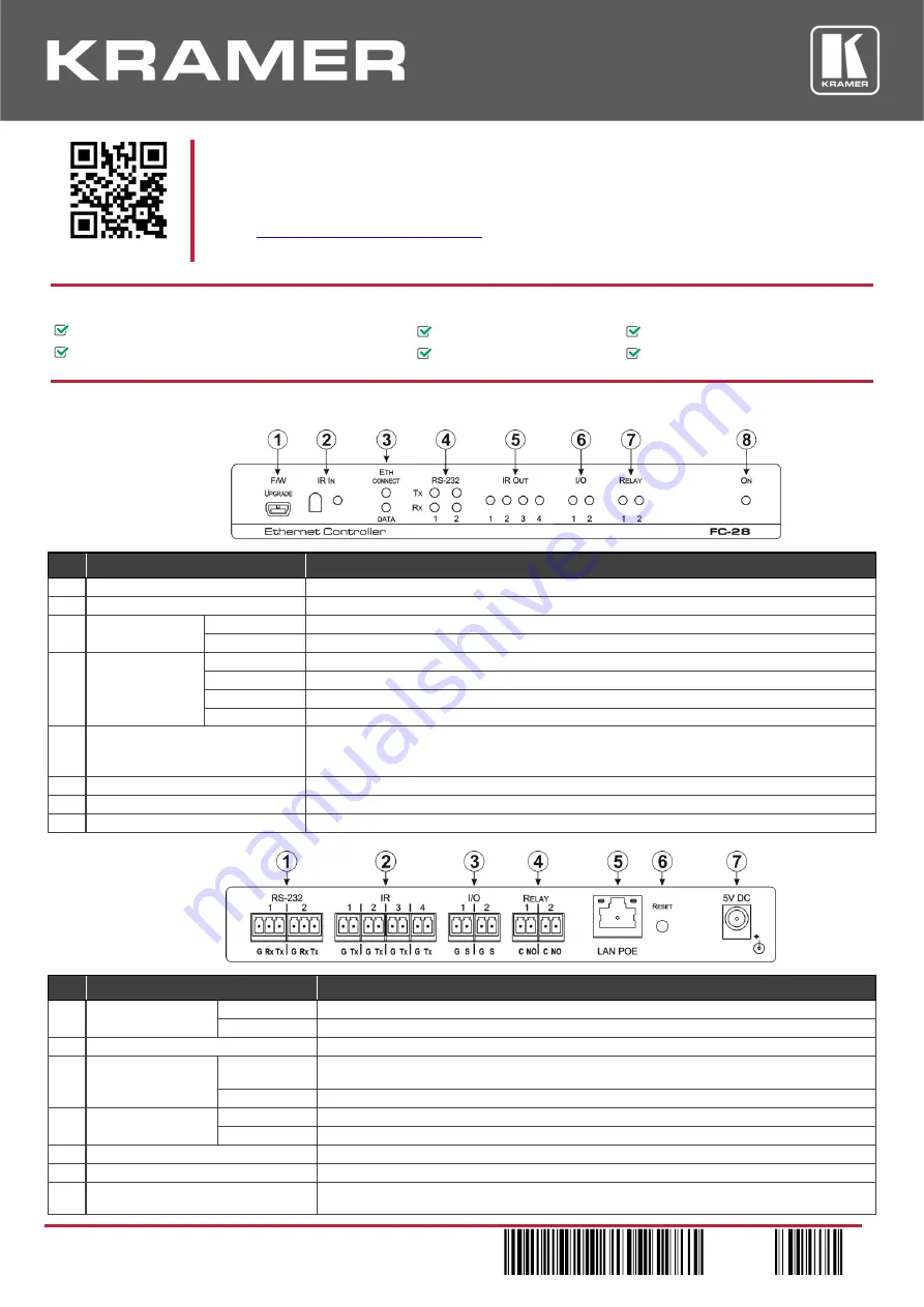
Front Panel
#
Feature
Function
1
F/W UPGRADE Mini USB Connector
Connect to a PC to perform a firmware upgrade
2
IR IN Sensor
Sensor for IR learning
3
ETH LEDs
CONNECT
Lights orange when the Ethernet port is connected
DATA
Flashes green when data is transferred over the Ethernet link
4
RS-232 LEDs
TX 1
Lights green when data Is transmitted on serial port 1
RX 1
Lights red when data is received on serial port 1
TX 2
Lights green when data Is transmitted on serial port 2
RX 2
Lights red when data is received on serial port 2
5
IR OUT 1 ~ 4 LEDs
The associated LED lights green when the relevant IR port transmits data.
Note: When IR learning is in progress, the relevant IR Out LED lights and the
FC-28
is unavailable
for normal operation
6
I/O 1 ~ 2 LEDs
Lights green when the port is triggered
7
RELAY 1 ~ 2 LEDs
Lights green when the relay is closed
8
ON LED
Lights green when the unit is on
Rear Pane
#
Feature
Function
1
RS-232 Two 3-pin
Terminal Blocks
1
Connect to the first RS-232 controlled device
2
Connect to the second RS-232 controlled device
2
IR 1 ~ 4 Four 2-pin Terminal Blocks
Connect to IR blasters/emitters using cables up to 80m (260ft) long
3
I/O Two 2-pin
Terminal Blocks
1
Connect to sensors or devices to be controlled, (for example, a motion sensor). Port may be
configured as a digital input, digital output, or analog input
2
Connect to the second sensor or device to be controlled
4
RELAY Two 2-pin
Terminal Blocks
1
Connect to the first device to be controlled by relay, (for example, a motorized projection screen)
2
Connect to the second device to be controlled by relay
5
LAN POE RJ-45 Connector
Connect to a PC or other controller directly or via a LAN
6
RESET Button
Press and hold while power-cycling the device to reset to factory default parameters
7
5V DC Connector
Connect to the 5V DC power supply, center pin positive. External power supply is not needed when
the device is supplied power by a PoE provider