

Step 3: Mount FC-18
Install
FC-18
using one of the following methods:
•
Attach the rubber feet and place the unit on a flat surface.
•
Fasten a bracket (included) on each side of the unit and attach it to a flat surface
(see
www.kramerav.com/downloads/FC-18
•
Mount the unit in a rack using the recommended rack adapter
(see
www.kramerav.com/product/FC-18).
•
Ensure that the environment (e.g., maximum ambient temperature &
air flow) is compatible for the device.
•
Avoid uneven mechanical loading.
•
Appropriate consideration of equipment nameplate ratings should be
used for avoiding overloading of the circuits.
•
Reliable earthing of rack-mounted equipment should be maintained.
•
Maximum mounting height for the device is 2 meters.
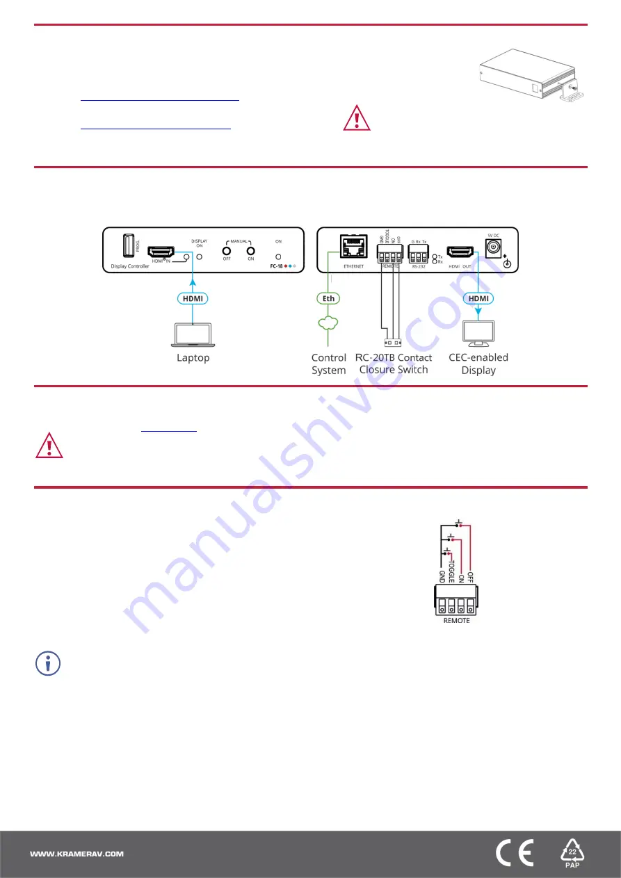
Step 4: Connect the input and output
Always switch OFF the power on each device before connecting it to your
FC-18
. For best results, we recommend that you
always use Kramer high-performance cables to connect AV equipment to
FC-18
.
Step 5: Connect the power
Connect the power cord to
FC-18
and plug it into the mains electricity.
Safety Instructions (See
for updated safety information)
Caution:
•
For products with relay terminals and GPI\O ports, please refer to the permitted rating for an external connection, located next to the terminal or in the User Manual.
•
There are no operator serviceable parts inside the unit.
Warning:
•
Use only the power cord that is supplied with the unit.
•
Disconnect the power and unplug the unit from the wall before installing.
Step 6: Control and Operate FC-18
Contact Closure Remote Control
Turn the display ON or OFF (or TOGGLE between ON and OFF) via the contact
closure remote control (also known as push-to-make momentary contact).
For example, to select ON, momentarily connect the ON pin to the GND pin.
Use the MANUAL front panel buttons and/or remote contact closure switch to turn
the display ON or OFF.
Setup and Control Using the Embedded Web Pages
Press the ON and OFF buttons on the front panel simultaneously to show the current IP address of
FC-18 on the display.
•
Set the RS-232 communication parameters and codes. These will typically be configured according to the RS-232
protocol of the display that the device controls when RS-
232 is set as an “output” port, or configured according to the
controller’s codes when RS-232 is set as an “input” port.
•
Select of the trigger mechanisms (5V, clock and sync signals in the HDMI input) which fire the RS-232 commands.
•
Set the delay times before the RS-232 codes are sent.
•
Set up the unit to send codes via Ethernet instead of RS-232 (for example to support applications where the projector
control is via Ethernet, not RS-232).
•
Configure tunneling parameters.
•
Enable / disable any of the control mechanisms (for example, disabling the front-panel buttons, or the automatic
control).


