background image

Using the Detachable Optical DVI System 


5

5.2  Connecting the Detachable Optical DVI Transmitter/Receiver 

To


connect the 

610T 

Detachable Optical DVI Transmitter

 with the 

610R 

Detachable Optical DVI Receiver

, as the example in Figure 3 illustrates, do 

the following: 
1.  Set the EDID of the display device (see section 5.1). 
2.  Plug the 

610T

 DVI connector 

directly

1

 to the DVI connector of the computer. 

3.  Connect the 

610R

 to the 5V DC power adapter and connect the adapter to the 

mains electricity. 

4.  Connect the 

610R

 DVI connector 

directly

1

 to the DVI connector of the 

display device. 

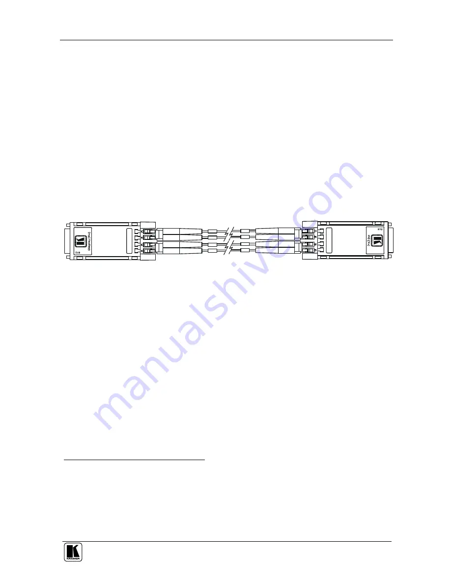
5.  Connect the duplex LC fiber cables

2

 to the 

610T 

and 

610R

 modules, one 

cable at a time, as illustrated in Figure 2. 

610R Receiver

610T Transmitter

1

2

1

2

3

4

3

4

1  

2  

3  

4

 3

  2

  1


Figure 2: Connecting the Fiber Optic Cables 

6.  Turn ON the Power on the computer and the display device. 
7.  If the transmitter does not power up, connect the 5V power adapter

3

 to the 

610T

 transmitter, and connect the adapter to the mains electricity. 

8.  Set up the screen resolution as required. 


1 Do not use any intermediate cable or adapter between them 

2  Two  duplex  LC  receptacles  connected  to  two  duplex  LC  patch  cord  multimode  glass  of  fibers  with  a  62.5/125 m  or  a 

50/125 m core 
3  You  can  use  the  power  supplied  through  a  DVI  pin  from  the  graphic  cards  instead  of  using  the  power  adapter.  After 
completing the installation, if the system does not seem to work properly, reconnect the power adapter while the system is 
powered 

Summary of Contents for 610R

Page 1: ...Kramer Electronics Ltd USER MANUAL Models 610T Detachable Optical DVI Transmitter 610R Detachable Optical DVI Receiver ...

Page 2: ...ining EDID 4 5 1 2 Capturing the Virtual EDID 4 5 2 Connecting the Detachable Optical DVI Transmitter Receiver 5 5 3 Avoiding Pitfalls using the 610T and 610R 6 6 Technical Specifications 7 Figures Figure 1 610 Detachable Optical DVI Transmitter and Receiver 3 Figure 2 Connecting the Fiber Optic Cables 5 Figure 3 Connecting the 610T 610R Detachable Optical DVI Transmitter Receiver 6 Tables Table 1...

Page 3: ...rmation display LED signboards in streets and in stadiums Digital Signage The package includes the following items 610T Detachable Optical DVI and or 610R Detachable Optical DVI 2 Power adapters 5V DC Input and this user manual2 2 Getting Started We recommend that you Unpack the equipment carefully and save the original box and packaging materials for possible future shipment Review the contents o...

Page 4: ...A at 60Hz or 1 65Gbps bandwidth per graphic channel Transmits one red one green and one blue channel and one clock with a 1 pixel clock mode over the fiber optic cables with 2 duplex LC fiber connectors Complies with the limits for a Class A digital device pursuant to part 15 and 2 of FCC and CE Does not require any special memory size CPU speed and chipsets when using a computer To achieve the be...

Page 5: ...ed via the external power adapter and if so the internal power supply will be cut off The 610R module must always be powered by the power adapter Most laptops require that the external power adapter is used for the transmitter 4 Your Detachable Optical DVI Transmitter Receiver Figure 1 illustrates the 610T and 610R optical DVI extension system Power Adapter DVI Connector Optical Connector Optical ...

Page 6: ...he display the display size luminance data and for digital displays only the pixel mapping data 5 1 2 Capturing the Virtual EDID You can capture the EDID of the display device on the 610T so that when the computer connects to the 610T it will read the virtual EDID information and identify the display device This procedure is performed only once for the connected display device After storing the ED...

Page 7: ...dules one cable at a time as illustrated in Figure 2 610R Receiver 610T Transmitter 1 2 1 2 3 4 3 4 1 2 3 4 4 3 2 1 Figure 2 Connecting the Fiber Optic Cables 6 Turn ON the Power on the computer and the display device 7 If the transmitter does not power up connect the 5V power adapter3 to the 610T transmitter and connect the adapter to the mains electricity 8 Set up the screen resolution as requir...

Page 8: ...uter and the display device and be sure that the Transmitter and Receiver modules are correctly plugged into the computer and display device respectively Check if the computer and display are powered ON and properly booted Reset the system by unplugging and then replugging the Transmitter DVI port or Receiver DVI port and then reboot the system If the screen is distorted or displays noise Check if...

Page 9: ...NPUTS DVI IN 610T OUTPUTS DVI OUT 610R RESOLUTION Up to WUXGA 60Hz 1 65Gbps OPERATING TEMPERATURE 0 C to 50 C STORAGE TEMPERATURE 40 C to 85 C HUMIDITY 5 to 95 POWER SOURCE 5 VDC 500mA DIMENSIONS 3 8cm x 7 2cm x 1 9cm 1 5 x 2 83 x 0 75 W D H WEIGHT 0 14 kg 0 31 lbs approx ACCESSORIES 2 power supplies 1 Specifications are subject to change without notice ...

Page 10: ...s required the original dated invoice or a copy must be presented as proof of warranty coverage and should be included in any shipment of the product Please also include in any mailing a contact name company address and a description of the problem s 3 For the name of the nearest Kramer authorized service center consult your authorized dealer LIMITATION OF IMPLIED WARRANTIES All implied warranties...

Page 11: ...For the latest information on our products and a list of Kramer distributors visit our Web site www kramerelectronics com where updates to this user manual may be found We welcome your questions comments and feedback Caution Safety Warning Disconnect the unit from the power supply before opening servicing ...

Reviews: