background image

Appendix   Calibration

29

4.

Strike the outer edge of the head to check whether the 
head is tensioned evenly. If necessary, make fine 
adjustments to the tension.

note: 

After tuning, calibrate the head, rim, and pressure 

sensors, and adjust the sensitivity as desired (

See 

page 29

).

Calibration

Calibrating the WAVEDRUM is a process of adjusting the 
reference values and sensitivity to ensure that it will 
respond accurately, given the head tension and the state 
of the rim.
You should perform the calibration procedure if the 
WAVEDRUM does not respond accurately to pressure 
etc., or after you’ve tuned or replaced the drum head. 
You should also perform the calibration again if sound 
produced by other instruments makes the WAVEDRUM 
resonate to cause feedback or inappropriately trigger the 
drum sound.

Calibrating the head sensor

Here's how to calibrate the head sensor that responds 
when you strike the head.

1.

Hold down the BANK/MODE button and press button 
4 to enter Global mode.

2.

Press the BANK/MODE button (several times) to 
make the display indicate 

H

.

 ca

 (Head Calibration).

3.

Press button 1 to make the display indicate 

Lo

 and the 

value.

4.

Turn the VALUE knob to adjust the value so that your 
normal light strikes produce sound. As you raise this 
value, you’ll need to strike harder in order to produce 
sound.

5.

Press button 2 to make the display indicate 

SEn

 and 

the value.

6.

Turn the VALUE knob to adjust the value so that the 
normal dynamic range of your strikes produces the 
appropriate change in the sound. As you raise this 
value, the sensitivity will become coarser.

7.

Save the setting. Press the WRITE button twice. For 
details on saving, refer to 

page 9

.

Calibrating the rim sensor

Here's how to calibrate the rim sensor that responds 
when you strike the rim.
Follow the procedure above, but choose 

r

.

 ca

 (Rim Cali-

bration) and adjust the sensitivity appropriately for the 
rim.

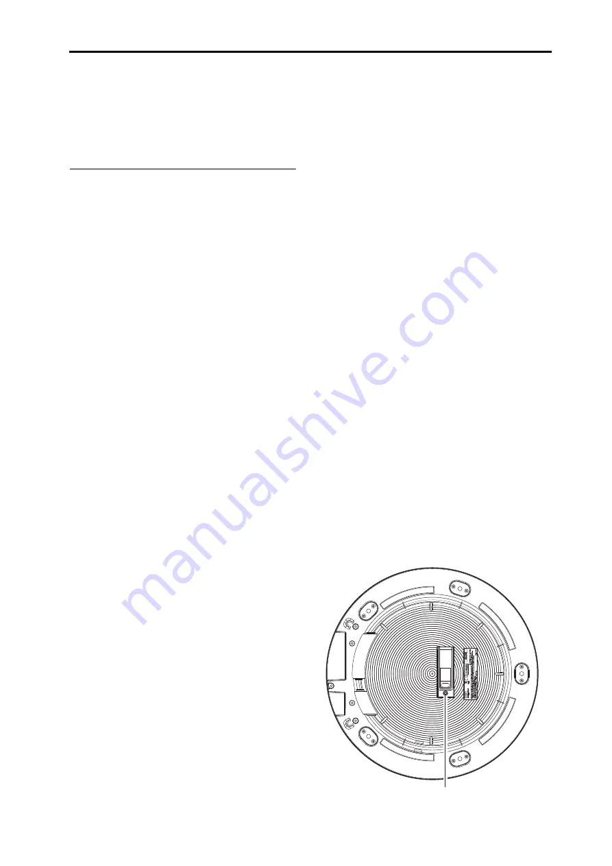
Calibrating the pressure sensor

Here’s how to calibrate the pressure sensor that response 
when you apply pressure to the head.

1.

Hold down the BANK/MODE button and press button 
4 to enter Global mode.

2.

Press the BANK/MODE button (several times) to 
make the display indicate 

P

.

 c a

 (Pressure Calibration).

3.

Press button 1 to make the display indicate  

UaL


(Value) and the value.

4.

Verify that the pressure sensor is set to an appropriate 
height. If either of the following situations apply, you 
must readjust the pressure sensor to an appropriate height.

If the sensor value indication is other than 0,

 the dis-

tance between the head and the sensor is too little, so 
the sensor must be lowered.

a.

 Insert the included Allen wrench into the sensor 

height adjustment screw, position the WAVEDRUM 
horizontally, and while watching the display, turn the 
wrench slowly counter-clockwise as seen from 
above, until the value is 0.

b.

 After the value reaches 0, turn the wrench an addi-

tional 45 degrees.

If the sensor value indication is 0, 

but the WAVE-

DRUM is not responsive to pressure, the distance 
between the head and the sensor is too great, so the 
sensor must be raised.

a.

 Insert the included Allen wrench into the sensor 

height adjustment screw, position the WAVEDRUM 
horizontally, and while watching the display, turn the 
wrench slowly clockwise.

b.

 When the sensor value indication is no longer 0, 

stop turning the wrench, and now turn the wrench in 
the opposite direction (counter-clockwise).

c.

 After the sensor value indication reaches 0, turn the 

wrench an additional 45 degrees.

5.

With the pressure sensor adjusted to an appropriate 
height, apply pressure to the head, and verify that the 
effect produced by pressure is within the desired range 
(minimum and maximum values). The current value is 
displayed when you press the head.

6.

Press button 2 to make the display indicate 

P

Lo

 and 

the value, and use the VALUE knob to specify the 
minimum value.

7.

Press button 3 to make the display indicate 

P

H i

 and 

the value, and use the VALUE knob to specify the 
maximum value.

8.

Save the setting. Press the WRITE button twice. For 
details on saving, refer to 

page 9

.

The WAVEDRUM's bottom 

Sensor height adjustment screw

Summary of Contents for Wavedrum

Page 1: ...1 Owner s Manual E 2 ...

Page 2: ...This equipment has been tested and found to comply with the limits for a Class B digital device pursuant to Part 15 of the FCC Rules These limits are designed to provide reasonable protection against harmful interference in a residential installation This equipment generates uses and can radiate radio fre quency energy and if not installed and used in accor dance with the instructions may cause ha...

Page 3: ...ble and continuous sound will result Feedback places severe stress on amps and speakers and can cause serious damage to equipment Thus when a powerful monitoring system is used the equalizers and limiters of the PA system should be adjusted to prevent the WAVEDRUM from producing feedback similar to preventing feedback for vocal and acoustic instrument mics Data handling Unexpected malfunctions can...

Page 4: ...uce a rich variety of sounds in addition to the algorithms Pro grams that use a single size algorithm allow you to freely assign a different algorithm and PCM instrument to the head and the rim giving you a very broad array of sounds Programs that use a double size algorithm are optimized for simulating acoustic instruments such as a snare djembe or cajon within the algorithm these pro grams analy...

Page 5: ... Head Rim DC IN connector Cable hook Cable hook OUTPUT L R jacks Power switch Headphone jack AUX IN jack another WAVEDRUM Powered monitors etc Audio player or Headphones INPUT OUTPUT to AC outlet AC adaptor included VOLUME knob Operating panel WRITE button Display VALUE knob Buttons 1 4 BANK MODE button ...

Page 6: ... con nected equipment is powered off and that all vol ume controls are set to 0 2 Power on the equipment that s connected to the AUX IN jack 3 Press the WAVEDRUM s power switch to turn it on When powering on the WAVEDRUM do not rest your hand or any other object on the head The WAVEDRUM may malfunction if this is the case 4 Turn on your powered monitors or other equip ment connected to the OUTPUT ...

Page 7: ...ll indicate the program number for the bank of the program that is currently selected 3 Press a button 1 4 to select the program that you want to play The indicator above the selected button will light up and the display will indicate the program number Strike the head or rim to hear the selected program 4 If you want to select a program from a different bank repeat steps 2 and 3 to select the des...

Page 8: ...gram In contrast the set tings in Global mode are common to the entire WAVEDRUM they are not specific to an individual program For details on each mode please refer to the respec tive reference pages The E1 E2 or G indicator at the right of the BANK MODE button will blink If you select Edit mode 1 or 2 the display will indi cate E d 1 or E d 2 and will then indicate the current page In Global mode...

Page 9: ... where the Tune parameter has a special role its specific function is described separately for each algorithm See pages 16 26 For PCM instruments you can adjust the pitch in semi tone steps in a range of four octaves up or down Edit 1 Decay d c Y This adjusts the time it takes for the sound to decay Like the Tune parameter there are cases where the Decay parameter will affect only the vibration of...

Page 10: ... Pan Level Pan Head Velocity Curve Head Single size Algorithm Amp Audio Line Stereo Audio Line Mono Pan Trigger Head PCM Instruments Output L R Phones L R Tune Decay Instruments Select Level Pan Level Pan Rim Velocity Curve Rim Single size Algorithm AUX IN Phrase Looper Trigger Rim PCM Instruments Level Level PressureSensor Rim Sensor Head Sensor Delay Program Double size AlgorithmType Reverb Pres...

Page 11: ...gnals sent to the mixer section are adjusted sent through reverb and delay and then sent out of the instrument Program structure for double size algorithms Double size algorithms are more highly specialized for simulating acoustic instruments For this reason two separate PCM instruments for the head and rim are combined into one allowing a larger amount of PCM data to be handled Within the algorit...

Page 12: ...m PCM instrument D 3 Level L E U h d A 0 0 0 1 0 0 S Specifies the volume of the head algorithm D Specifies the vol ume of the algorithm h d P 0 0 0 1 0 0 S Specifies the volume of the head PCM instru ment D r A 0 0 0 1 0 0 S Specifies the volume of the rim algorithm D r P 0 0 0 1 0 0 S Specifies the volume of the rim PCM instru ment D 4 Pan P a n h d A L 5 0 r 5 0 S Specifies the pan of the head ...

Page 13: ...ones up to 1 octave by which the pitch will change when the maximum pressure is applied D 9 Pressure Decay P dc h d P 5 0 5 0 S Specifies how the decay time of the head PCM instrument will be affected by pressure applied to the head This setting specifies the change produced when the maximum pressure is applied D r P 5 0 5 0 S Specifies how the decay time of the rim PCM instrument will be affected...

Page 14: ...o the algorithm Choose one of the following five combina tions according to how you re playing the WAVEDRUM H H You re using your hand to play both the head and the rim H S You re using your hand to play the head and a stick to play the rim S S You re using a stick to play both the head and the rim H n You re using your hand to play the head and the notches to play the rim S n You re using a stick...

Page 15: ...nd press button 4 to enter Global mode and press button 4 in the Co Common page note You can t change the playback speed of the loop phrase Page Parameter Button1 Button2 Button3 Button4 1 Common Co Pan L 5 0 r 5 0 Specifies the pan follow ing the delay effect L values place the sound to the left r values to the right and 00 places the sound in the center Default Value 0 A ln 0 0 0 1 0 0 Specifies...

Page 16: ...s algorithm have an important and complex effect on each other This means that modify ing the value of one parameter will change the way that the other parameters affect the sound Tune 50 Decay 97 hd1 rm1 Bell Color 000 100 60 As this value is increased the sound will become brighter and as it is decreased the sound will become darker hd2 rm2 Harmonic Shift 50 50 0 This parameter makes the overton...

Page 17: ...parameter adjusts the depth of the muting that occurs when you press the head hd8 rm8 Effects Level 000 100 30 As this value is increased there will be a more pro nounced stereo effect and the sound will become richer 05 Arimbao This algorithm produces the sound of a large double headed drum The sound consists of several different sounds a clear marimba like sound the sound of two skins front and ...

Page 18: ...t the volume balance between the pitched sound and the noise sound Positive settings will make the pitched sound louder and neg ative settings will make the noise sound louder hd4 rm4 Tone Decay 000 100 70 This parameter adjusts the decay time for the pitched sound hd5 rm5 Interval 000 100 10 This parameter adjusts the pitch difference between the two pitched sounds hd6 rm6 Noise Filter 000 100 10...

Page 19: ...ilter The pitch of the oscillation is determined by the Slap Filter parameter hd8 rm8 Threshold 000 100 25 This parameter adjusts the point where stronger hits on the edge of the head will begin to produce a noisy slap sound 11 Steel ST This algorithm produces the sound of the Berimbau a Brazilian instrument that consists of a hunting bow with a small gourd attached as a resonator and played by ta...

Page 20: ... volume balance of the sitar and tambura Negative settings will cause the sitar to be louder and positive settings will cause the tam bura to be louder hd4 rm4 Top Color 000 100 89 This parameter adjusts the tone color of the sitar Higher settings will produce a longer sustaining and brighter sound hd5 rm5 Drone Color 000 100 89 This parameter adjusts the tone color of the tambura Higher settings ...

Page 21: ...more high frequency clashing hd6 rm6 Harmonic Shift 000 100 90 This parameter adjusts the pitch differences between the various resonating bodies As this value is increased the pitch and overtone structure will change in complex ways hd7 rm7 Thickness 000 100 7 As this value is increased the sound will become lighter with a more pronounced high range As this value is decreased the sound will becom...

Page 22: ...djustments in the size of the jingle sound Negative settings will result in a muffled sound as if the bell was muted by being grasped in the hand Positive settings will let the sound expand changing to a sound similar to a wall clock strik ing the hour hd3 rm3 Repeat 000 100 89 This parameter allows you to set the length of time that the jingle will sound hd4 rm4 Bell Decay 000 100 83 This paramet...

Page 23: ...you strike with a cer tain range of force differences in striking force within that range will play different notes within an octave of the selected scale allowing you to play phrases Tune adjusts the basic pitch in chromatic steps over a range of 26 69 With a setting of 50 the pitch will be C You can select the type of scale and specify the range of striking force that corresponds to the octave o...

Page 24: ...eter adjusts the amount of portamento that connects each drum note hd5 rm5 Brightness 000 100 38 This parameter adjusts the tone color of the drum sound As this value is increased the sound will become more metallic and have a longer resonance hd6 rm6 Noise Color 000 100 40 This parameter adjusts the color of the noise that is heard when you apply pressure to the head Increasing this value will pr...

Page 25: ... adjusts how the amount of pressure that s applied to the head will affect the pitch or tonal charac ter hd2 Brightness 000 100 8 This parameter will radically adjust the tonal character of the snare drum Increasing this value will produce extended overtones that sound like a guitar or piano hd3 Ensemble Size 000 100 58 This parameter adjusts the de synchronization of the five snares As this value...

Page 26: ...er and positive settings make the PCM louder hd4 Sub Harmonics 000 100 This parameter adjusts the low frequency component of the sound Increasing this value will reduce the amount of low frequency producing a lighter and harder sound hd5 Brightness 000 100 Increasing this value will produce a sharper sound with more high frequencies hd6 Slap Level 000 100 This parameter adjusts the level of the vi...

Page 27: ...ng of 0 they will have the same volume Negative settings make the algo rithm louder and positive settings make the PCM louder hd4 Curve 000 100 This parameter adjusts the response of the shell to your strike and the resonance of the shell hd5 Brightness 000 100 Increasing this value will increase the high frequency components of the shell sound and the snare sound hd6 Snappy Decay 000 100 This par...

Page 28: ...original position and tighten the tension bolts For details on how to tighten them refer to the follow ing section Tuning the drum head 4 After you ve tuned the drum head calibrate the head rim and pressure sensors and adjust the sensitivity as desired See page 29 Tuning the drum head To tune the drum head use the included tuning key to tighten each tension bolt skipping one bolt each step to ensu...

Page 29: ...e the pressure sensor that response when you apply pressure to the head 1 Hold down the BANK MODE button and press button 4 to enter Global mode 2 Press the BANK MODE button several times to make the display indicate P c a Pressure Calibration 3 Press button 1 to make the display indicate UaL Value and the value 4 Verify that the pressure sensor is set to an appropriate height If either of the fol...

Page 30: ...strument The sound of another instrument causes the WAVE DRUM to resonate and be triggered unintentionally You may be able to prevent this by calibrating the head See page 29 Feedback occurs Consider using an equalizer or limiter of your PA sys tem to prevent feedback and protect the amp and speaker system See page 3 You may be able to prevent this by calibrating the head See page 29 Does not resp...

Page 31: ...igning 7 audio devices 6 AUX IN 6 15 B bank 7 C calibration 15 29 common 15 D decay 9 12 delay 13 double size algorithm 11 26 playing 26 drum head 28 E Edit 1 8 12 Edit 2 8 14 Editing 8 F factory settings 28 feedback 3 30 G Global 8 15 H hand 14 I input 6 L level 12 Live mode 7 loop phrase 15 volume 15 N notches 14 O OUTPUT L R 6 P pan 12 15 PCM instrument 11 12 Performing 7 power on 6 pre EQ 14 p...

Page 32: ...ed thisproduct via the internet through mail order and or via a telephone sale you must verify that this product isintended to be used in the country in which you reside WARNING Use of this product in any country other than that for which it is intended could be dangerousand could invalidate the manufacturer s or distributor s warranty Please also retain your receipt as proof of purchase otherwise...

Reviews: