154
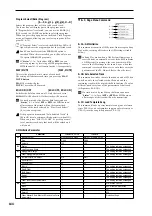
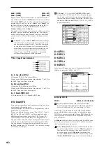
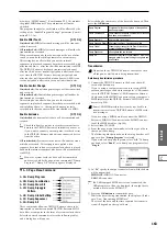
9–5a: VALVE FORCE
Input Trim
[000...127]
Ultra Boost
[000...127]
Tube Gain
[000...127]
Output Level
[000...127]
These parameters set the input to Valve Force, the amount of
ultra-low-frequency boost, the input gain to the vacuum
tube, and the output level from Valve Force.
For details on these parameters, refer to Program mode.
As in Program mode, you can use MIDI NRPN control
change messages to control the VALVE FORCE [ON/
OFF] key and the parameters (knobs) listed above.
However, the MIDI channel used for control will be the
“Ctrl Ch”.
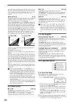
Placement
[Final, Insert (User 3/4 BUS)]
Specifies the location of the Valve Force circuit.
For details on this parameter, refer to Program mode.
You cannot apply Valve Force to the S/P DIF output,
which is processed as a digital signal.
Here’s an example of settings when you’ve set “Placement”
to Insert (Use 3/4 BUS) in Song Play mode.
Example settings)
Set “BUS Select” (8–1(2)b) or post-IFX “BUS Sel.” (8–3a) to
insert Valve Force at the desired location. Use Valve Force
“BUS Sel.” (9–5a) to specify the output destination from
Valve Force.
• Track
→
Valve Force
→
audio output
“BUS Select”: 3/4(Tube)
Valve Force “BUS Sel.”: L/R or 1/2
You can send more than one track to Valve Force. How-
ever you can’t make Valve Force settings independently
for each track.
• Track
→
Valve Force
→
insert effect
→
master effects
→
audio output
“BUS Select”: 3/4(Tube)
Valve Force “BUS Sel.”: IFX1...5
Post-IFX “Send1,” “Send2”: as desired
Post-IFX “BUS Sel.”: L/R or 1/2
Don’t set the post-IFX “BUS Sel.” to 3/4(Tube), since
doing will cause a feedback loop that may produce
unpleasant distortion.
• Track
→
insert effect
→
Valve Force
→
master effects
→
audio output
“BUS Select”: IFX1...5
Post-IFX “BUS Sel.”: 3/4(Tube)
Valve Force “BUS Sel.”: L/R or 1/2
Valve Force “Send1,” “Send2”: as desired
• Track
→
insert effect
→
Valve Force
→
insert effect
→
master effects
→
audio output
“BUS Select”: IFX1...5
Post-IFX “BUS Sel.”: 3/4(Tube)
Valve Force “BUS Sel.”: IFX1...5
Post-IFX “Send1,” “Send2”: as desired
Post-IFX “BUS Sel.”: L/R or 1/2
Don’t set the post-IFX “BUS Sel.” to any preceding IFX,
since doing so will cause a feedback loop that may pro-
duce unpleasant distortion.
In the same way, you can insert Valve Force into the
input from Audio Input.
Ctrl Ch (Control Channel)
[Ch01...16, Gch]
Specifies the MIDI channel on which Valve Force will be
controlled.
Gch:
Control using the global MIDI channel specified by
“MIDI Channel” (Global P1).
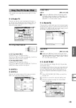
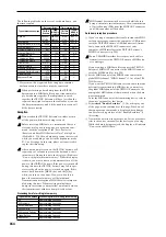
9–5b: Post VALVE FORCE Mixer
Pan(CC#8)
[L000...C064...R127]
BUS Sel.
[L/R, IFX1...5, 1, 2, 1/2, Off]
Send1
[000...127]
Send2
[000...127]
ADC OVERLOAD !!
These parameters specify the destination to which the Valve
Force output is sent.
Refer to Program mode for details on these parameters.
As in Program mode, you can use CC#8 to control “Pan
(CC#8),” CC#93 to control “Send1,” and CC#93 to con-
trol “Send2.” However, the MIDI channel used for con-
trol will be the “Ctrl Ch”.
“Pan,” “BUS Sel.”, “Send1,” “Send2,” and “ADC
OVERLOAD !!” apply only if “Placement” is set to
Insert (Use 3/4 BUS).
▼
9–5: Page Menu Command
9–5A
0–1E
Summary of Contents for TRITON Extreme
Page 1: ...2 E ...
Page 11: ...xii ...
Page 111: ...100 9 5 Page Menu Command 0 1A 0 1I 0 1J Program 9 5A ...
Page 185: ...174 ...
Page 215: ...204 ...
Page 281: ...270 ...
Page 349: ...338 ...
Page 350: ...339 ...
Page 351: ...340 ...
Page 352: ...341 ...
Page 353: ...342 ...


